
Manufacturing method of magnetic film annular inductor

A technology of toroidal inductors and magnetic thin films, applied in the application of magnetic films to substrates, inductance/transformer/magnet manufacturing, circuits, etc., can solve the problems of incompatibility with semiconductor processes and the inability of thin film inductors to achieve high inductance density, etc. Achieve the effect of realizing large-scale production, low environmental and equipment requirements, and high quality factor

Inactive Publication Date: 2020-07-10
UNIV OF ELECTRONICS SCI & TECH OF CHINA
View PDF9 Cites 2 Cited by
  • Summary
  • Abstract
  • Description
  • Claims
  • Application Information

AI Technical Summary

Problems solved by technology

[0006] The purpose of the present invention is to provide a method for manufacturing a ring inductor based on an isotropic magnetic film, aiming at the problems that the thin film inductors in the background technology cannot achieve high inductance density and high quality factor, and are not compatible with semiconductor technology

Method used


Image

  • Manufacturing method of magnetic film annular inductor
  • Manufacturing method of magnetic film annular inductor
  • Manufacturing method of magnetic film annular inductor

Examples


Embodiment 1

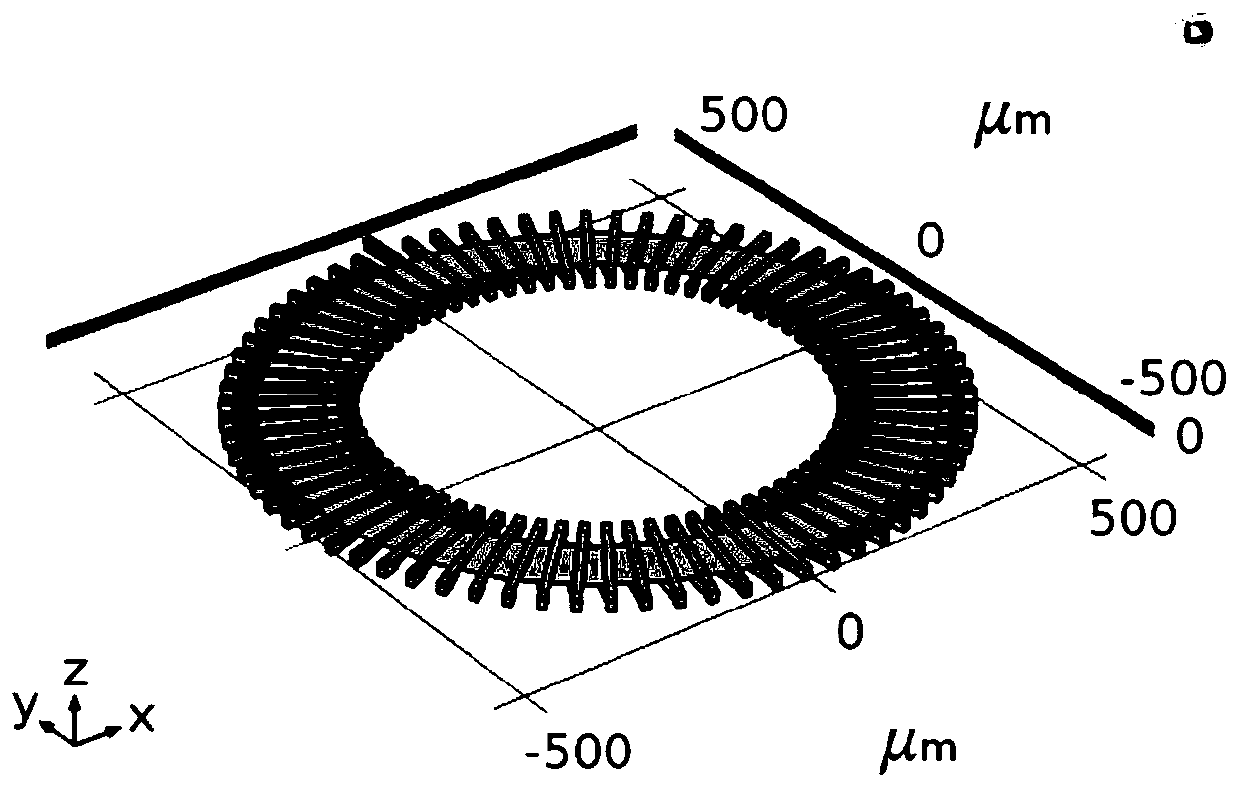
[0034] The invention provides a method for preparing a magnetic thin film toroidal inductor, the simulation model of the magnetic thin film toroidal inductor is as follows figure 1As shown, from bottom to top are silicon substrate, silicon dioxide insulating layer, lower coil, polyimide support layer, magnetic core film, polyimide support layer, upper coil, the upper coil and the lower coil pass through Holes are connected to obtain a copper coil. Wherein, the total number of turns of the copper coil is 72 turns, and the pitch of each turn is 5 degrees.

Embodiment

[0035] The preparation method of embodiment magnetic film ring inductor specifically comprises the following steps:

[0036] Step 1. Deposit a layer of 500nm thick silicon dioxide insulating layer on the high-resistance silicon substrate, then use the electroplating process to make the lower coil, and then deposit a layer of polyimide as the insulating support layer;

[0037] Step 2, preparing a magnetic core film by a spin spraying method;

[0038] 2.1 Sodium nitrite (NaNO 2 ) and sodium acetate (CH 3 COONa) was added into 1L of deionized water, and mixed uniformly to obtain the oxidation solution;

[0039] 2.2 Ferrous chloride (FeCl 2 ), nickel chloride (NiCl 2 ) and zinc chloride (ZnCl 2 ) into deionized water to prepare a reducing solution; the specific formulations of the oxidizing solution and the reducing solution are shown in Table 1-1:

[0040] Table 1-1

[0041]

[0042]

[0043] 2.3 Use an ultrasonic atomization system with an ultrasonic source power of...

Embodiment 2~4

[0049] The specific formulations of the oxidation solution and the reduction solution in steps 2.1 and 2.2 were changed, as shown in Table 1-2, to obtain Examples 2-4; other parameters and conditions of Examples 2-4 were the same as Example 1.

[0050] The formula of oxidation solution and reduction solution in table 1-2 embodiment 2~4

[0051]

[0052] The inductors prepared in Examples 1-4 were tested, and it was found that the Zn content in the film of Example 1 was the highest, so that the NiZn ferrite film had higher magnetization power and lower magnetization resistance, and the film permeability was higher , according to the ion occupancy distribution of spinel ferrite, Zn 2+ ions preferentially occupy the A site, with the Zn 2+ The increase of , the static magnetic moment of the material increases, and at the same time, the density of the film increases, and the saturation magnetization of the film increases. Therefore, by adjusting the Zn content in the film to o...


PUM

PropertyMeasurementUnit
thicknessaaaaaaaaaa
thicknessaaaaaaaaaa
widthaaaaaaaaaa

Abstract

The invention discloses a manufacturing method of a magnetic film annular inductor, and belongs to the technical field of inductor manufacturing. The method comprises the steps of firstly, manufacturing a lower-layer coil on a substrate; then, preparing a magnetic core film by adopting a rotary spraying method; finally, manufacturing an upper-layer coil on the obtained magnetic core film, and theannular inductor can be obtained. The invention provides a manufacturing method of a magnetic thin film annular inductor. The high-frequency soft magnetic isotropic thin film is adopted as the magnetic core thin film, the magnetic core thin film is prepared through a rotary spraying method, crystallization can be completed in air at 90 DEG C, on one hand, production energy consumption is low, preparation of the magnetic core thin film can be completed through a low-temperature deposition technology, the requirement for the environment and equipment is low, and large-scale production can be achieved; and on the other hand, the annular inductor obtained by the method has high inductance density, high working frequency and high quality factor, and can be compatible with a semiconductor process.

Description

technical field [0001] The invention belongs to the technical field of inductor manufacturing, and in particular relates to a manufacturing method of a magnetic film ring inductor compatible with semiconductor technology. Background technique [0002] With the rapid development of information technology, following Moore's Law, electronic products are constantly upgraded, the size of electronic systems is getting smaller and smaller, the integration and operating frequency are getting higher and higher, and more and more functions are integrated in the system. Correspondingly, various electronic components are also developing in the direction of miniaturization, high frequency, planarization, high stability, high precision, and low loss. Inductors are important passive devices that implement functions such as filtering, tuning, amplification, and impedance coupling. At present, electronic components such as resistors and capacitors have been integrated, only magnetic devices...

Claims


Application Information

Patent Timeline
Patent Type & Authority Applications(China)
IPC IPC(8): H01F41/04H01F41/18H01F41/22H01F41/00
CPCH01F41/00H01F41/04H01F41/183H01F41/22
Inventor 孙科郑璐刘海余忠邬传健蒋晓娜兰中文
Owner UNIV OF ELECTRONICS SCI & TECH OF CHINA
Learn More