Sandwich structure giant magneto-impedance effect composite material and preparation method

A technology of giant magneto-impedance and composite materials, applied in the field of magnetic sensitive components, can solve the problems such as the inability of the giant magneto-impedance value to be significantly improved and the magnetic flux path to be unable to be well closed, to enhance the GMI effect, suitable for mass production, The effect of increasing sensitivity

Active Publication Date: 2021-02-09
EAST CHINA NORMAL UNIVERSITY
6 Cites 1 Cited by

AI-Extracted Technical Summary

Problems solved by technology

However, due to the existence of stray fields and flux leakage, the magnetic flux path cann...

Abstract

The invention discloses a sandwich structure giant magneto-impedance effect composite material and a preparation method. According to the preparation method, a reduced graphene oxide (rGO) inner layeris synthesized on a nanocrystalline Fe73.5. 5Cu1Nb3Si13B9.5 strip of a sensitive element of a giant magneto-impedance sensor through one-step chemical plating, a FeCo outer layer is obtained througha magnetron sputtering method, and the giant magneto-impedance (GMI) effect composite of the FeCo/rGO/FINEMET/rGO/FeCo sandwich structure is obtained. The invention has the beneficial effects that onone hand, the reduced graphene oxide layer is used as a high-conductivity layer, a channel beneficial to high-frequency current flowing is provided, and the skin effect is greatly reduced; on the other hand, the FeCo layer increases the magnetic conductivity, and a closed magnetic circuit is provided. Finally, the giant magneto-impedance (GMI) effect composite material with the FeCo/rGO/FINEMET/rGO/FeCo sandwich structure obtains a remarkably enhanced GMI effect, the sensitivity of the GMI sensor is also improved, the process is simple, and the giant magneto-impedance composite material is suitable for mass production.

Application Domain

Magnetic-field-controlled resistorsGalvano-magnetic material selection +1

Technology Topic

Image

  • Sandwich structure giant magneto-impedance effect composite material and preparation method
  • Sandwich structure giant magneto-impedance effect composite material and preparation method
  • Sandwich structure giant magneto-impedance effect composite material and preparation method

Examples

  • Experimental program(4)

Example Embodiment

[0028]Example 1
[0029]Step 1: Take iron-based amorphous Fe73.5Cu1Nb3Si13B9.5One strip
[0030]Step 2: Place the iron-based amorphous ribbon of step 1 in a tube furnace, set the vacuum to 1.5pa, heat up to 540°C, pass in 5 sccm of hydrogen, and anneal for 20 minutes to obtain the iron-based nanocrystalline ribbon;
[0031]Step 3: Place the iron-based nanocrystalline strips obtained in step 2 in 0.4M NaOH, 0.5 M Na2CO3And 0.7M Na3PO4·12H2Degreasing and cleaning treatment in the O mixed solution, the treatment time is 10 minutes;
[0032]Step 4: Place the strip obtained in step 3 in a 5M HCl solution for acidification treatment, the treatment time is 20 minutes;
[0033]Step 5: Place the strip obtained in step 4 in 0.3M SnCl2· 2H2Sensitization is carried out in a mixed solution of O and 0.6M HCl, and the treatment time is 20 minutes;
[0034]Step 6: Place the strip obtained in step 5 on 2.5×10⁻⁴M PdCl2Activate it in a mixed solution of 0.6M HCl, and the processing time is 20 minutes;
[0035]Step 7: Disperse a single layer of graphene oxide powder in deionized water, and configure a graphene oxide aqueous solution with a concentration of 70 mg/L;
[0036]Step 8: Adjust the pH value of the graphene oxide aqueous solution to 12 with NaOH solution;
[0037]Step 9: Add hydrazine hydrate to the graphene oxide aqueous solution obtained in step 8, and configure a mixed solution with a mass concentration ratio of graphene and hydrazine hydrate of 1:1550 mg/L;
[0038]Step 10: Place the iron-based nanocrystal strips obtained in step 6 in the mixed solution of step 9, and place them in a water bath at 90°C, heat and react in the water bath, the reaction time is 40 minutes; take out the sample after the end, Prepare rGO/FINEMET/rGO strips;
[0039]Step 11: Place the rGO/FINEMET/rGO strip obtained in step 10 in a magnetron sputtering vacuum chamber, and adjust the vacuum to 1.5×10⁻⁴Pa;
[0040]Step 12: Pass 20sccm of Ar into the vacuum chamber, and press the pressure to 1.9Pa, and start to deposit the FeCo layer with a power of 60w. Under this condition, a 40nm FeCo layer was sputtered to prepare the sandwich structure giant magneto-impedance (GMI) effect composite material FeCo/rGO/FINEMET/rGO/FeCo.
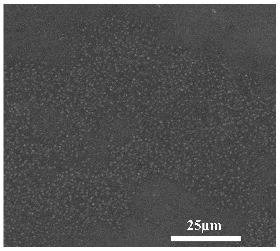
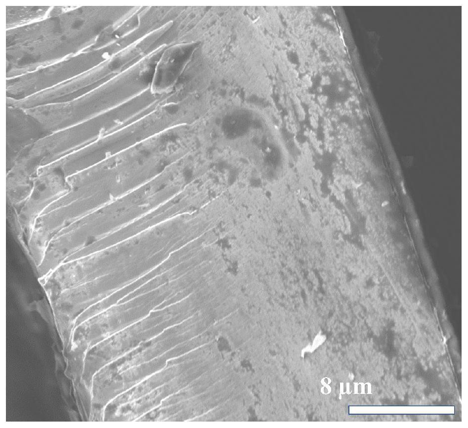
[0041]The surface SEM morphology of the sandwich structure giant magneto-impedance (GMI) effect composite material prepared in Example 1 is shownimage 3 , See the cross-sectional SEM topographyFigure 4 , See the spectrogramFigure 7. FromFigure 7It can be seen that the impedance value of the giant magneto-impedance (GMI) effect composite material prepared by the present invention is increased from 34.64% to 70.32%.

Example Embodiment

[0042]Example 2
[0043]Step 1: Take iron-based amorphous Fe73.5Cu1Nb3Si13B9.5One strip
[0044]Step 2: Place the iron-based amorphous ribbon of step 1 in a tube furnace, set the vacuum to 1.9pa, heat up to 540°C, pass in 5 sccm of hydrogen, and anneal for 20 minutes to obtain the iron-based nanocrystalline ribbon;
[0045]Step 3: Place the iron-based nanocrystalline strips obtained in step 2 in 0.4M NaOH, 0.5 M Na2CO3And 0.7M Na3PO4·12H2Degreasing and cleaning treatment in the O mixed solution, the treatment time is 20 minutes;
[0046]Step 4: Place the strip obtained in step 3 in a 5M HCl solution for acidification treatment, the treatment time is 20 minutes;
[0047]Step 5: Place the strip obtained in step 4 in 0.3M SnCl2· 2H2Sensitization is carried out in a mixed solution of O and 0.6M HCl, and the treatment time is 20 minutes;
[0048]Step 6: Place the strip obtained in step 5 on 2.5×10⁻⁴M PdCl2Activate it in a mixed solution of 0.6M HCl, and the processing time is 20 minutes;
[0049]Step 7: Disperse the single-layer graphene oxide powder in deionized water, and configure a graphene oxide aqueous solution with a concentration of 50 mg/L;
[0050]Step 8: Adjust the pH value of the graphene oxide aqueous solution to 12.5 with NaOH solution;
[0051]Step 9: Add hydrazine hydrate to the graphene oxide aqueous solution obtained in step 8, and configure a mixed solution with a mass concentration ratio of graphene and hydrazine hydrate of 1:2300 mg/L;
[0052]Step 10: Place the iron-based nanocrystalline strips obtained in Step 6 in the mixed solution of Step 9, and place them in a water bath at 90°C, heat and react in the water bath, the reaction time is 50 minutes; after the end, take out the sample, Prepare rGO/FINEMET/rGO strips;
[0053]Step 11: Place the rGO/FINEMET/rGO strip obtained in step 10 in a magnetron sputtering vacuum chamber, and adjust the vacuum to 1.5×10⁻⁴Pa;
[0054]Step 12: Pass 20sccm of Ar into the vacuum chamber, and press the pressure to 1.9Pa, and start to deposit the FeCo layer with a power of 60w. Under this condition, a 50nm FeCo layer was sputtered to prepare the sandwich structure giant magneto-impedance (GMI) effect composite material FeCo/rGO/FINEMET/rGO/FeCo.
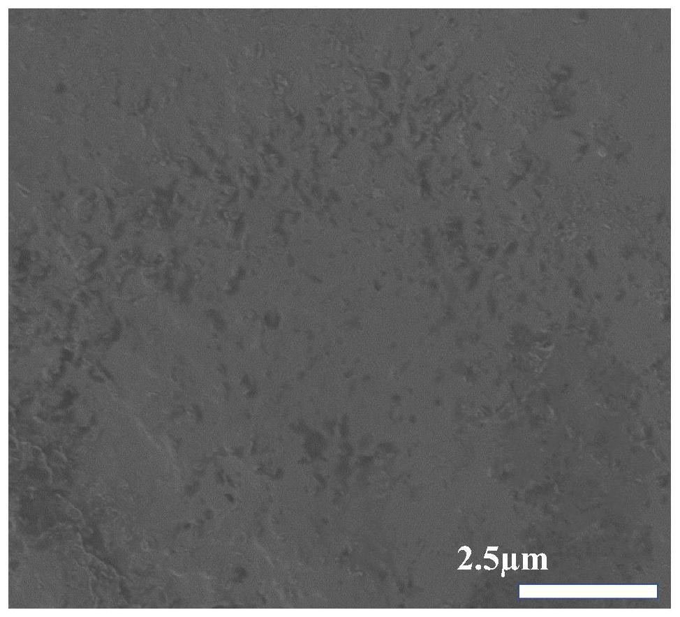
[0055]The surface SEM morphology of the sandwich structure giant magneto-impedance (GMI) effect composite material prepared in Example 2 is shownFigure 5 , See the cross-sectional SEM topographyImage 6 , See the spectrogramFigure 7. FromFigure 7It can be seen that the impedance value of the giant magneto-impedance (GMI) effect composite material prepared by the present invention is increased from 34.64% to 59.7%.

Example Embodiment

[0056]Example 3
[0057]Step 1: Take iron-based amorphous Fe73.5Cu1Nb3Si13B9.5One strip
[0058]Step 2: Place the iron-based amorphous ribbon of step 1 in a tube furnace, set the vacuum to 2pa, heat up to 540°C, pass in 5 sccm of hydrogen, and anneal for 20 minutes to obtain the iron-based nanocrystalline ribbon;
[0059]Step 3: Place the iron-based nanocrystalline strips obtained in step 2 in 0.4M NaOH, 0.5 M Na2CO3And 0.7M Na3PO4·12H2Degreasing and cleaning treatment in the O mixed solution, the treatment time is 10 minutes;
[0060]Step 4: Place the strip obtained in step 3 in a 5M HCl solution for acidification treatment, the treatment time is 20 minutes;
[0061]Step 5: Place the strip obtained in step 4 in 0.3M SnCl2· 2H2Sensitization is carried out in a mixed solution of O and 0.6M HCl, and the treatment time is 10 minutes;
[0062]Step 6: Place the strip obtained in step 5 on 2.5×10⁻⁴M PdCl2Activate it in a mixed solution of 0.6M HCl, and the processing time is 20 minutes;
[0063]Step 7: Take a single layer of graphene oxide powder and disperse it in deionized water, and configure a graphene oxide aqueous solution with a concentration of 80 mg/L;
[0064]Step 8: Adjust the pH value of the graphene oxide aqueous solution to 11 with NaOH solution;
[0065]Step 9: Add hydrazine hydrate to the graphene oxide aqueous solution obtained in Step 8, and configure a mixed solution with a mass concentration ratio of graphene and hydrazine hydrate of 1:1800 mg/L;
[0066]Step 10: Place the iron-based nanocrystalline strips obtained in Step 6 in the mixed solution of Step 9, and place them in a water bath at 80°C, heat and react in the water bath, the reaction time is 30 minutes; after the end, take out the sample, Prepare rGO/FINEMET/rGO strips;
[0067]Step 11: Place the rGO/FINEMET/rGO strip obtained in step 10 in a magnetron sputtering vacuum chamber, and adjust the vacuum to 1.5×10⁻⁴Pa;
[0068]Step 12: Pass 20sccm of Ar into the vacuum chamber, and press the pressure to 1.9Pa, and start to deposit the FeCo layer with a power of 60w. Under this condition, a 30nm FeCo layer was sputtered to prepare the sandwich structure giant magneto-impedance (GMI) effect composite material FeCo/rGO/FINEMET/rGO/FeCo.

PUM

PropertyMeasurementUnit
Concentration10.0 ~ 100.0mg/l
tensileMPa
Particle sizePa
strength10

Description & Claims & Application Information

We can also present the details of the Description, Claims and Application information to help users get a comprehensive understanding of the technical details of the patent, such as background art, summary of invention, brief description of drawings, description of embodiments, and other original content. On the other hand, users can also determine the specific scope of protection of the technology through the list of claims; as well as understand the changes in the life cycle of the technology with the presentation of the patent timeline. Login to view more.

Similar technology patents

Flat wire winding, motor stator, and motor

PendingCN109301963AReduce skin effectSavings on winding materialMagnetic circuit stationary partsWindings conductor shape/form/constructionSkin effectStator
Owner:GREE ELECTRIC APPLIANCES INC OF ZHUHAI

Transmission line surge diversion grounding device

ActiveCN109616786AReduce skin effectThe surface current density is smallConnection contact member materialSkin effectPower equipment
Owner:STATE GRID SHANDONG ELECTRIC POWER +1

Coil of wireless power transmission system and winding method thereof

PendingCN113707440AReduce skin effectReduce AC internal resistanceTransformersCircuit arrangementsSkin effectTransmission system
Owner:GUANGXI POWER GRID ELECTRIC POWER RES INST

Novel busbar

PendingCN109390851AReduce thicknessReduce skin effectBus-bar/wiring layoutsBus-bar installationBusbarEngineering
Owner:ZHENJINAG KLOCKNER MOELLER ELECTRICAL SYST CO LTD

Classification and recommendation of technical efficacy words

  • High permeability
  • Reduce skin effect

Hydraulic fracturing composition, method for making and use of same

ActiveUS20150096751A1High permeabilityEnhance productionFluid removalMixingSuperabsorbent polymerBuffering agent
Owner:BAKER HUGHES INC

Large ampacity cable

Owner:ANHUI HUAXING CABLE GROUP

Method for winding dynamic analogue element by adopting stranded conductors

InactiveCN101615507AReduce skin effectMeet the simulation requirementsEducational modelsCoils manufactureSkin effectDynamic simulation
Owner:CHINA ELECTRIC POWER RES INST +1

Inductive coupling device and semiconductor processing device

ActiveCN111192812AReduce skin effectImproving Inductive Coupling Power Utilization EfficiencyElectric discharge tubesPhysicsHigh power density
Owner:BEIJING NAURA MICROELECTRONICS EQUIP CO LTD

High-frequency wire and manufacturing method thereof

InactiveCN106205839AEffective transpositionReduce skin effectInsulated cablesInsulated conductorsSkin effectEngineering
Owner:株洲市科达电机技术有限公司

Water-cooled reactor

Owner:TAIYAO ELECTRONICS PRODS SUZHOU
Why Eureka
Try Eureka