Solid electrolyte composite layer and lithium ion battery

A solid-state electrolyte and lithium-ion battery technology, applied in the field of lithium-ion batteries, can solve the problems of large grain boundary resistance, poor physical contact, and low ionic conductivity at room temperature.

Inactive Publication Date: 2021-04-02
ZHUHAI COSMX BATTERY CO LTD
View PDF6 Cites 13 Cited by
  • Summary
  • Abstract
  • Description
  • Claims
  • Application Information

AI Technical Summary

Problems solved by technology

Among them, the inorganic ceramic solid electrolyte has the advantages of good ionic conductivity, negligible electronic conductivity, and wide electrochemical window, but its own large grain boundary resistance and poor physical contact with the positive and negative electrodes ; The organic polymer solid electrolyte has good flexibility and processability, but the ionic conductivity at room temperature is too low, and lithium dendrites are easy to pierce the electrolyte and cause a short circuit in the battery; the inorganic ceramic / polymer composite solid electrolyte is a combination of inorganic ceramic solid electrolyte and polymer The advantages of solid-state electrolytes not only maintain a strong lithium ion transport capacity, but also avoid the potential short circuit caused by lithium dendrites piercing the electrolyte. However, the commonly used composite method is to uniformly mix inorganic ceramic powder and polymer matrix. This composite method is not easy to adjust precisely according to the requirements of high voltage resistance on the positive side and stable compatibility with lithium metal on the negative side.

Method used


Image

  • Solid electrolyte composite layer and lithium ion battery
  • Solid electrolyte composite layer and lithium ion battery
  • Solid electrolyte composite layer and lithium ion battery

Examples


Embodiment 1

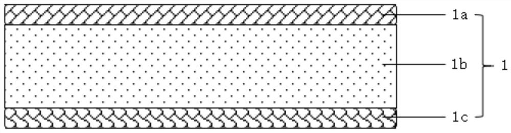
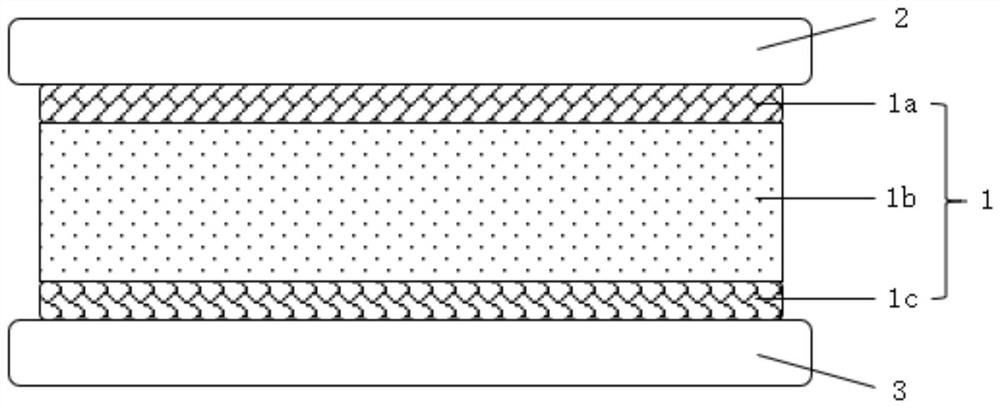
[0070] The solid electrolyte composite layer and lithium-ion battery structure of this embodiment refer to figure 1 with figure 2 , the preparation method is as follows:

[0071] 1. Preparation of solid electrolyte composite layer 1

[0072] 1) According to the traditional solid-state sintering method, the NASICON-type electrolyte Li 1.5 Al 0.5 Ti 1.5 (PO 4 ) 3 , after drying, put it into a mold and press it into a thin sheet, sinter at 900°C for 6 hours and then cool to obtain the intermediate solid electrolyte layer 1b.

[0073] 2) Polyacrylonitrile (PAN), LiClO 4 Dissolve in DMF according to the mass ratio of 2:1, stir evenly at a rotating speed of 600rpm to obtain a slurry near the positive electrode side with a solid content of 11%, and apply the positive electrode side slurry to the middle solid electrolyte layer 1b near the positive electrode sheet 2 On the functional surface, fully vacuum-dry the positive electrode side solid electrolyte 1a at 80°C for 10h, wh...

Embodiment 2

[0080] The solid electrolyte composite layer and lithium-ion battery structure of this embodiment refer to figure 1 with figure 2 , the preparation method is as follows:

[0081] 1. Preparation of solid electrolyte composite layer 1

[0082] 1) The commercially available perovskite electrolyte Li 3x La 2 / 3-x TiO 3 (x=0.11) after drying, put it into a mold and press it into a thin sheet, sinter at 950° C. for 4 hours and then cool to obtain the intermediate solid electrolyte layer 1b.

[0083] 2) Dissolve polycaprolactone (PCL), LiDTI, and succinonitrile in THF at a mass ratio of 7:3:1.1, and stir evenly at 400 rpm to obtain a slurry near the positive electrode with a solid content of 23%, which is close to the positive electrode. The side slurry is coated on the functional surface of the intermediate solid electrolyte layer 1b close to the positive electrode sheet 2, and fully vacuum-dried at 50°C for 3 hours to obtain the solid electrolyte 1a near the positive electrode...

Embodiment 3

[0090] The solid electrolyte composite layer and lithium-ion battery structure of this embodiment refer to figure 1 with figure 2 , the preparation method is as follows:

[0091] 1. Preparation of solid electrolyte composite layer 1

[0092] 1) According to the traditional solid-state sintering method, the garnet-type electrolyte Li 6.6 La 3 Zr 1.6 Ta 0.4 o 12 , after drying, put it into a mold and press it into a thin sheet, sinter at 1200°C for 3 hours and then cool to obtain the intermediate solid electrolyte layer 1b.

[0093] 2) Polyvinylene carbonate (PVCA) and LiFSI were dissolved in chloroform according to the mass ratio of 5:3, and stirred evenly at 900rpm to obtain a slurry near the positive side with a solid content of 12%. The material is coated on the functional surface of the intermediate solid electrolyte layer 1b close to the positive electrode sheet 2, and fully vacuum-dried at 25°C for 6 hours to obtain the solid electrolyte layer 1a near the positive...


PUM


Abstract

The invention provides a solid electrolyte composite layer and a lithium ion battery. The solid-state electrolyte composite layer comprises a near-positive-electrode-side solid-state electrolyte layer, a middle solid-state electrolyte layer and a near-negative-electrode-side solid-state electrolyte layer which are sequentially arranged in a stacked mode. The middle solid-state electrolyte layer comprises the inorganic ceramic electrolyte, the near-positive-electrode-side solid electrolyte layer comprises near-positive-electrode-side polymer with high oxidation resistance, and the near-negative-electrode-side solid electrolyte layer comprises a near-negative-electrode-side compound stable with metal lithium, so that the solid electrolyte composite layer is high in mechanical strength, and lithium dendrites are prevented from piercing the electrolyte; the requirements of high-voltage resistance of a positive electrode side and stability of a negative electrode side and metal lithium aremet, and meanwhile, the interface wettability of the solid electrolyte composite layer is good. The lithium ion battery comprises the solid electrolyte composite layer, and due to the fact that the solid electrolyte composite layer is high in mechanical strength, excellent in wettability and good in stability with positive and negative electrode interfaces, the lithium ion battery has the advantages of being small in battery internal resistance, good in cycle performance and high in safety.

Description

technical field [0001] The invention belongs to the field of lithium ion batteries, and relates to a solid electrolyte composite layer and a lithium ion battery. Background technique [0002] In recent years, among various commercial rechargeable and dischargeable chemical energy storage devices, lithium-ion batteries have the characteristics of high energy density and long service life, and have been widely used in mobile phones, notebook computers, electric vehicles and other fields. At present, most of the electrolytes used in lithium-ion batteries are liquid organic electrolytes. Liquid organic electrolytes are volatile, flammable and explosive, which seriously affects the safety of lithium-ion batteries during use. [0003] Solid-state electrolytes have high mechanical strength, excellent density, and the ability to resist the growth of lithium dendrites, and have no volatile, flammable and explosive characteristics of liquid organic electrolytes. Therefore, if solid-st...

Claims


Application Information

Patent Timeline
Patent Type & Authority Applications(China)
IPC IPC(8): H01M10/0565H01M10/0525H01M10/42
CPCH01M10/0525H01M10/0565H01M10/4235H01M2300/0085Y02E60/10
Inventor 张赵帅赵伟李素丽
Owner ZHUHAI COSMX BATTERY CO LTD
Why Eureka
Try Eureka