Electromagnetic auxiliary stamping incremental forming process for thin-wall curved-surface light alloy component

A light alloy, incremental forming technology, applied in the field of electromagnetic-assisted stamping incremental forming process of thin-walled curved light alloy components, can solve the problems of easy cracking, high sealing requirements, and large post-spin residual stress, etc., to achieve improved Microstructure uniformity and formability, good flexibility and expandability, and the effect of improving the forming limit

Inactive Publication Date: 2021-07-09
WUHAN UNIV OF TECH
View PDF6 Cites 1 Cited by
  • Summary
  • Abstract
  • Description
  • Claims
  • Application Information

AI Technical Summary

Problems solved by technology

However, light alloy materials have poor formability at room temperature and are difficult-to-form materials; large thin-walled curved parts such as rocket fuel tank bottoms have poor structural rigidity and are difficult-to-form structures
[0003] Aiming at the difficulties in manufacturing the bottom parts of rocket fuel storage tanks, one of the technical solutions adopted in the prior art is "tailored welded thick plate + hot spinning + CNC milling", but there are complex processes, long manufacturing cycles, and serious waste of materials (waste rate above 90%) and other issues
The second technical solution adopted in the prior art is: split forming→aging treatment→welding→milling. In actual operation, this process needs to change the forming equipment and heat treatment equipment many times, and the melon petals have poor plasticity and large springback. It makes the welding of melon parts difficult and the internal stress after welding is large, resulting in problems such as poor dimensional accuracy, high rejection rate, and low reliability.
Although the spinning forming and internal high pressure forming methods can realize integral forming, the spinning process is prone to defects such as cracking and wrinkling, and there are complex process control, large residual stress after spinning, and significant residual deformation after quenching, etc. Problem; while internal high pressure forming has extremely high requirements on the tonnage of the hydroforming machine and the tightness of the high-pressure liquid. At present, the maximum diameter that can be formed is about 3m, which limits its application in large curved surface components.

Method used


Image

  • Electromagnetic auxiliary stamping incremental forming process for thin-wall curved-surface light alloy component
  • Electromagnetic auxiliary stamping incremental forming process for thin-wall curved-surface light alloy component
  • Electromagnetic auxiliary stamping incremental forming process for thin-wall curved-surface light alloy component

Examples


Embodiment 1

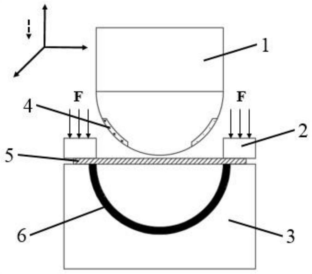
[0036] For the high-strength alloy after heat treatment, place it on the mold platform 3, fix it with the clamping system 2, move the punch 1 embedded with the driving forming coil 4 to make it go down until the punch 1 and the plate to be formed The material 5 is just in contact with each other, and it is pre-deformed by punch 1 as a whole, and the pre-deformation amount is 10-30% of the total deformation amount. In places where the local fluidity is not good, the capacitor bank is used to realize charging and discharging, so that the formed coil 4. With a pulse current of 20-100kA, the forming coil 4 embedded in the punch 1 is used to discharge to form a strong pulse Lorentz force, and the pre-deformed sheet is punched at high speed, so that the sheet to be formed 5 is locally deformed at a high speed , so as to complete the final shape of the part. If the final shape requirements of the parts are not met, the forming coil 4 can be discharged again to perform electromagnetic...

Embodiment 2

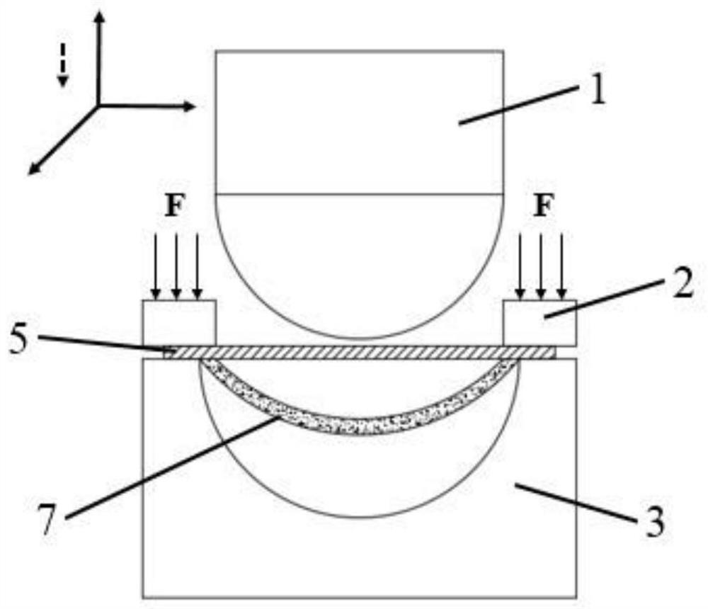
[0038] For the high-strength alloy after heat treatment, place it on the mold platform 3, fix it with the clamping system 2, move the punch 1 to make it go down, until the punch 1 and the sheet material 5 to be formed are just in contact with each other. Pre-deformed by punch 1 as a whole, the amount of pre-deformation is 10-30% of the total deformation, and the pre-stamped sheet 7 is obtained. The specific forming schematic diagram is shown in Fig. Replace it with one or more flexible coils 8 that can move and rotate along three axes. According to the preset trajectory, the flexible coils 8 are discharged along the trajectory in turn to form a strong pulse Lorentz force, and the pre-deformed sheet is stamped at high speed. , compared with the traditional punch 1, the flexible coil 8 is smaller in size and more flexible. It is gradually formed through multi-pass coil superposition and discharge until it meets the shape accuracy requirements of the part. The specific forming sch...

Embodiment 3

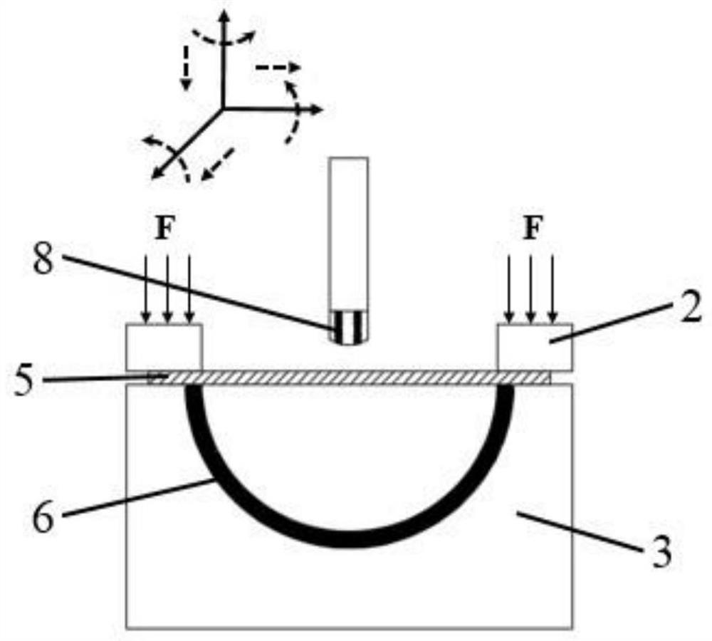
[0040]First, the overall stamping and pre-deformation, followed by solid solution single-stage aging or solid solution double-stage aging heat treatment, and then use the coil placed in the punch, or one or more small flexible follow-up coils, discharge to form a strong Lorentzian pulse Force, high-speed impact stamping the pre-deformed sheet, multi-pass electromagnetic progressive forming, until the shape accuracy requirements of the parts are met. The specific processing process of molding scheme three is as follows: Figure 4 shown.

[0041] Electromagnetic-assisted stamping progressive forming can actively control the local forming of the sheet to be formed by changing the layout and moving track of the driving forming coil. The strength and toughness of the alloy realize the integrated and precise forming tonality of large thin-walled curved surface components of light alloys.


PUM


Abstract

The invention relates to an electromagnetic auxiliary stamping incremental forming process for a thin-wall curved-surface light alloy component. The electromagnetic auxiliary stamping incremental forming process comprises the following steps that S1, solid solution aging treatment is conducted on a light alloy plate; S2, the light alloy plate is subjected to pre-stamping, and the pre-stamping deformation amount is 10%-30% of the total deformation amount; and S3, a forming coil is used for discharging to form pulse Lorentz force, the plate obtained after pre-stamping deformation is impacted, multi-pass electromagnetic incremental forming is carried out, and final forming of the thin-wall curved-surface light alloy component is completed. The sequence of the step S1 and the step S2 can be interchanged. The large thin-wall curved-surface component manufactured through the electromagnetic auxiliary stamping incremental forming process for the thin-wall curved-surface light alloy component is good in formability, high in precision and excellent in surface quality, and the comprehensive mechanical property is greatly improved.

Description

technical field [0001] The invention relates to the field of light alloy forming and manufacturing, and more specifically relates to an electromagnetic-assisted stamping progressive forming process for a thin-walled curved surface light alloy component. Background technique [0002] The launch vehicle is an indispensable tool for human beings to carry out space activities such as lunar exploration projects, space station construction, and deep space exploration. The diameter of the fuel tank directly determines the carrying capacity of the rocket, and for the launch vehicle, the economic benefit obtained by reducing the weight by 1kg is nearly 100,000 US dollars. Therefore, the demand for high-performance lightweight materials and large thin-walled lightweight structures for the bottom parts of rocket fuel tanks known as the "rocket crown" is becoming more and more urgent. High-strength lightweight alloys (represented by aluminum alloys, titanium alloys, magnesium alloys, e...

Claims


Application Information

Patent Timeline
Patent Type & Authority Applications(China)
IPC IPC(8): B21D26/14C22F1/04C22F1/06C22F1/18
CPCB21D26/14C22F1/04C22F1/06C22F1/183
Inventor 马慧娟冒文杰崔旭华胡志力华林
Owner WUHAN UNIV OF TECH
Why Eureka
Try Eureka