Method and system for continuously producing cell/electrolytic cell and battery/electrolytic cell

An electrolytic cell and battery technology, which is applied in the direction of battery electrodes, fuel cell parts, fuel cells, etc., can solve the problems of low battery yield, high manual error, and complicated operating procedures, so as to achieve continuous production and reduce poor performance. Effect of stabilizing phenomena and improving yield

Pending Publication Date: 2021-07-23
XI AN JIAOTONG UNIV
View PDF0 Cites 1 Cited by
  • Summary
  • Abstract
  • Description
  • Claims
  • Application Information

AI Technical Summary

Problems solved by technology

[0004] However, as far as the solid oxide fuel cell / electrolytic cell is concerned, there are still many technical problems that have not been effectively resolved in the production and preparation process.
For example, the existing production process is mostly manual operation or staged operation, and this type of operation has high manual error, complex operation procedures, low degree of mechanization and automation, low battery yield rate, and difficult to control the stability of battery performance, etc. question
Not only that, the production technology of solid oxide fuel cells / electrolyzers supported by porous metals is rarely mentioned in this field; moreover, how to produce solid oxide fuel cells / electrolytic cells supported by porous metals The problems of improving its yield and maintaining battery stability during the preparation process have not been effectively resolved so far.

Method used


Image

  • Method and system for continuously producing cell/electrolytic cell and battery/electrolytic cell
  • Method and system for continuously producing cell/electrolytic cell and battery/electrolytic cell

Examples


Embodiment 1

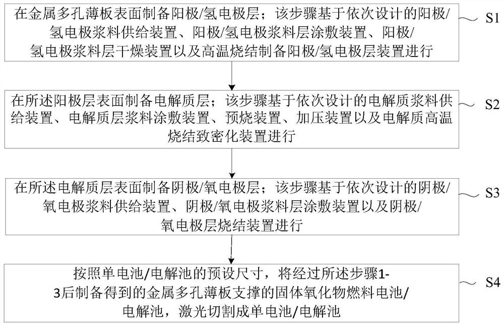
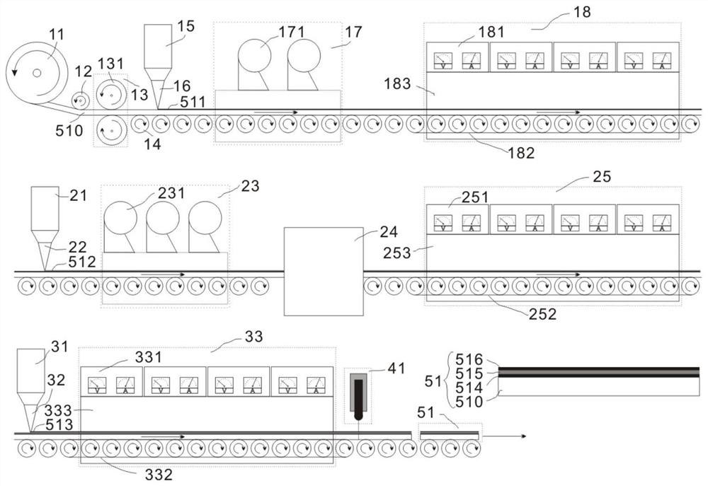
[0101] Firstly, a ferritic stainless steel plate with a chromium content of 18wt%, a porosity of 15%, and a thickness of 50 μm is selected as the material of the metal porous sheet support body, and the bent ferritic stainless steel plate is rolled by a sheet coil flattening device. Made into a flat ferritic stainless steel plate, that is, a metal porous sheet support. After passing through the conveying rollers, the metal porous thin plate support body is sent to the anode preparation area.

[0102] In the anode preparation area, a layer of NiO-GDC anode slurry layer containing a quantitative pore-forming agent is coated on the surface of the metal porous sheet support by the anode slurry layer coating device, and then passed through the anode slurry layer drying device at 90 °C for drying. After drying, it is sintered at 1000° C. in an anode layer high-temperature sintering device to form a porous anode layer with a thickness of 30 μm. Then, the metal porous thin plate sup...

Embodiment 2

[0106]First, a ferritic stainless steel plate with a chromium content of 25wt%, a porosity of 45%, and a thickness of 200 μm is selected as the material of the metal porous sheet support body, and the bent ferritic stainless steel plate is rolled by a sheet coil flattening device. Made into a flat ferritic stainless steel plate, that is, a metal porous sheet support. After passing through the conveying rollers, the metal porous thin plate support body is sent to the anode preparation area.

[0107] In the anode preparation area, a layer of NiO-GDC anode slurry layer containing a quantitative pore-forming agent is coated on the surface of the metal porous sheet support by an anode slurry layer coating device, and then passed through an anode slurry layer drying device at 80 °C for drying. After drying, it is sintered at 1050°C in a high-temperature sintering device for the anode layer to form a porous anode layer, and the thickness of the anode is 30 μm. Then, the metal porou...

Embodiment 3

[0111] Firstly, a ferritic stainless steel plate with a chromium content of 35wt%, a porosity of 60%, and a thickness of 350 μm is selected as the material of the metal porous sheet support body, and the bent ferritic stainless steel plate is rolled by a sheet coil flattening device. Made into a flat ferritic stainless steel plate, that is, a metal porous sheet support. After passing through the conveying rollers, the metal porous thin plate support body is sent to the anode preparation area.

[0112] In the anode preparation area, a layer of NiO-ScSZ anode slurry layer containing a quantitative pore-forming agent is coated on the surface of the metal porous sheet support by an anode slurry layer coating device, and then passed through an anode slurry layer drying device at 100 °C for drying. After drying, it is sintered at 1200°C in a high-temperature sintering device for the anode layer to form a porous anode layer with a thickness of 50 μm. Then, the metal porous thin pla...


PUM

PropertyMeasurementUnit
Thicknessaaaaaaaaaa
Thicknessaaaaaaaaaa
Thicknessaaaaaaaaaa

Abstract

The invention provides a method and system for continuously producing a cell / electrolytic cell and the cell / electrolytic cell. The method comprises the step of sequentially preparing an anode (hydrogen electrode) layer, an electrolyte layer and a cathode (oxygen electrode) layer on a metal porous thin plate supporting body. The method provided by the invention comprises the steps of firstly, taking a metal porous thin plate as a pressure-bearing supporting body in a continuous production line, then regulating and controlling the thickness of an anode (hydrogen electrode) layer, selectively removing a solvent and part of a binder in an electrolyte slurry layer, and carrying out pressure sintering densification treatment on an electrolyte layer, thereby solving problems that the automation degree is low, the yield is low, and the performance stability is poor in the technology of continuously producing the solid oxide fuel cell / electrolytic cell supported by the metal sheet. Therefore, according to the method provided by the invention, the continuous production of the solid oxide fuel cell / electrolytic tank can be realized, the production process is simplified, the production efficiency and the yield are improved, and the method has a wide commercial application prospect.

Description

technical field [0001] The invention relates to the technical field of solid oxide fuel cell production equipment, in particular to a method, system and battery / electrolytic cell for continuous production of batteries / electrolytic cells. Background technique [0002] As a new energy conversion device, the fuel cell can maximize the conversion of chemical energy into electrical energy because it is not affected by the Carnot cycle. It has higher power generation efficiency. In addition, the common raw materials of fuel cells are fuel and oxygen, with high fuel conversion efficiency and less harmful gas emissions, which is in line with national sustainable development and environmental protection requirements. Due to its excellent portability and good stability, fuel cells are expected to be widely used in stationary power stations, portable power generation devices, and transportation. [0003] In recent years, solid oxide fuel cells have been used in many types of fuel cel...

Claims


Application Information

Patent Timeline
IPC IPC(8): H01M8/0276H01M8/0282H01M8/12H01M8/1226H01M8/1231H01M8/124H01M4/88C25B9/00C25B11/031C25B11/04
CPCH01M8/0276H01M8/0282H01M8/1226H01M8/1231H01M8/124H01M4/8803H01M4/8828H01M4/8882H01M4/8885H01M8/12C25B9/00H01M2008/1293Y02P70/50Y02E60/50
Inventor 李成新李延安李娇苏康思远
Owner XI AN JIAOTONG UNIV
Why Eureka
Try Eureka