Method for preparing polyurethane-based composite electrolyte membrane and polyurethane-based composite electrolyte membrane

A composite electrolyte membrane and polyurethane technology, which is applied in composite electrolytes, circuits, electrical components, etc., can solve problems such as poor mechanical properties, difficulty in meeting the mechanical strength requirements of the diaphragm, weak ability to dissolve lithium salts and complex lithium ions, etc.

Active Publication Date: 2021-09-14
ZHEJIANG NARADA POWER SOURCE CO LTD +1
View PDF6 Cites 0 Cited by
  • Summary
  • Abstract
  • Description
  • Claims
  • Application Information

AI Technical Summary

Problems solved by technology

However, the polarity of the Si-O bond is low, the ability to dissolve lithium salts and complex lithium ions is weak, and the mechanical properties are poor. It is difficult to make a

Method used


Image

  • Method for preparing polyurethane-based composite electrolyte membrane and polyurethane-based composite electrolyte membrane
  • Method for preparing polyurethane-based composite electrolyte membrane and polyurethane-based composite electrolyte membrane
  • Method for preparing polyurethane-based composite electrolyte membrane and polyurethane-based composite electrolyte membrane

Examples


Embodiment 1

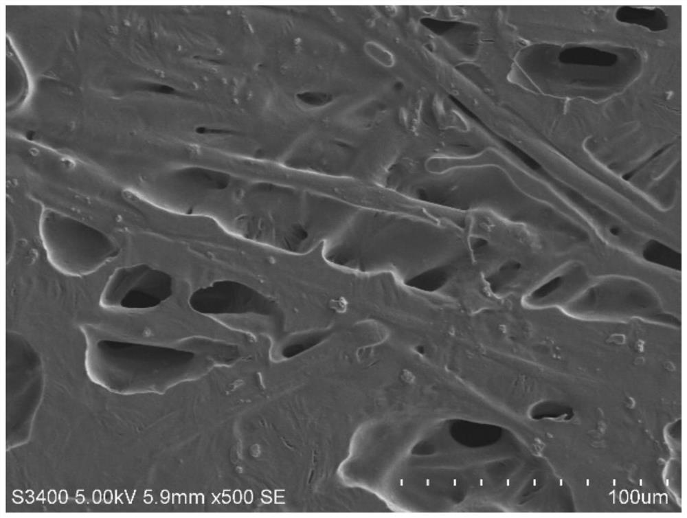
[0038] Step 3: After mixing the PU-PDMS copolymer prepared in the above step 2 and the mass ratio of 30% (30% of the mass of the mass of the PU-PDMS copolymer), add a twin screw extruder, extruded out The machine heating temperature was 170 ° C, the meltblown mold spray hole diameter was 0.4 mm, the mold temperature was 170 ° C, the hot air temperature was 200 ° C, the air pressure was 0.3 Ml, the flow rate was 4.5 ml / min. The reinforcing fiber material is PP, and the PP meltblown mold spine is 0.4 mm, the mold temperature is 250 ° C, the hot air temperature is 280 ° C, the air pressure is 0.3 Ml, PP melt flow rate 2 mL / min. The fiber wire ejected from the two modes is uniformly mixed in the air, and the rending distance of the die spinfiring pores will be 25cm, the receiving device is 80-120m / min, and the fiber diameter is At 1-5 μm.

[0039] Step 4: The mixed fiber filament passes through a pressure roll of 50-150 ° C, adjusting the pressure roller pressure and temperature...

Embodiment 2

[0042] Step 3: After mixing the PU-PDMS copolymer prepared in the above step 2 and the mass ratio of the lithium salt Litfsi of 30%, the double screw extruder is added, the extruder heating temperature is 170 ° C, the meltblown mold spray hole diameter is 0.4 MM, mold temperature 170 ° C, hot air temperature 200 ° C, gas pressure 0.3 MPa, and polymer flow of 4.5 ml / min. The PP meltblown mold spray hole is 0.4 mm, the mold temperature is 250 ° C, the hot air temperature is 280 ° C, the air pressure is 0.3 Ml, and the PP melt flow rate is 2 ml / min. The fiber wire ejected from the two turbines is uniformly mixed in the air, and the receiving device of the die spinheet pores will be 25 cm, the receiving device is 40-80 m / min, the fiber diameter is 1-5 μm.

[0043] Step 4: The mixed fiber filament passes through a pressure roll of 50-150 ° C, adjusting the pressure roller pressure and temperature, melting the polyurethane-polysiloxane-based polymer in the mixed fiber layer togeth...

Embodiment 3

[0045] Step 3: After mixing the PU-PDMS copolymer prepared in step 2 and the mass than 30% lithium salt grafsi is mixed and uniformly added to the twin screw extruder, the extruder heating temperature 150 ° C, the meltblown mold spine is 0.4mm The mold temperature is 150 ° C, the hot air temperature is 200 ° C, the air pressure is 0.3 MPa, and the polymer flow is 4.5 ml / min. The reinforcing fiber material is PP, and the PP meltblown mold spine is 0.4 mm, the mold temperature is 250 ° C, the hot air temperature is 280 ° C, the air pressure is 0.3 Ml, PP melt flow rate 2 mL / min. The fiber wire ejected from the two modes is uniformly mixed in the air, and the rending distance of the die spinfiring pores is 25 cm, the receiving device is 80-120 m / min, the fiber diameter is in the fiber diameter. 1-6 μm.

[0046] Step 4: The mixed fiber filament passes through a pressure roll of 50-150 ° C, adjusting the pressure roller pressure and temperature, melting the polyurethane-polysilox...


PUM

PropertyMeasurementUnit
Fiber diameteraaaaaaaaaa
Movement speedaaaaaaaaaa
Melt indexaaaaaaaaaa

Abstract

The invention provides a preparation method of a polyurethane-based composite electrolyte membrane and a polyurethane-based composite electrolyte membrane. The preparation method of the polyurethane-based composite electrolyte membrane comprises a uniform mixing and dispersing step, a melt-blowing step and a hot roller pressurizing step. According to the uniform mixing and dispersing step,a polyurethane-polysiloxane block copolymer and a lithium salt are mixed and dispersed, heating is performed to obtain a lithium salt mixture. According to the melt-blowing step, the lithium salt mixture and reinforced fibers are simultaneously mixed and interwoven by adopting a melt-blowing process, and then an obtained product sets on a receiving device to form a composite fiber non-woven fabric; According to the hot roller pressurization step, hot roller pressurization is carried out on the composite fiber non-woven fabric to obtain the polyurethane-based composite electrolyte membrane.

Description

Technical field [0001] The present invention relates to the field of lithium ion battery, especially a polyurethane group composite electrolyte membrane, and a polyurethane group composite electrolyte membrane. Background technique [0002] Commercial lithium-ion batteries have a large safety hazard due to the use of easy volatile, easy to combustion, and probabilized organic liquid electrolytes. The full solid-state lithium-ion battery has a certain mechanical strength to replace the organic liquid electrolyte and porous diaphragm, which can avoid the safety problems caused by the liquid electrolyte, and there is also an advantage of high energy density and simple processing molding. [0003] Among them, the solid polymer electrolyte is expected to achieve commercial use due to the advantages of good flexibility, interfacial compatibility and applicable large area processing. Polyethylene oxide (PEO) is widely studied in polymer electrolytes due to its very good lithium salt sol...

Claims


Application Information

Patent Timeline
IPC IPC(8): H01M10/0565H01M10/0525
CPCH01M10/0565H01M10/0525H01M2300/0088Y02E60/10
Inventor 张焱陈建刘桃松陈冬屠芳芳党志敏张文李敏胡雨萌
Owner ZHEJIANG NARADA POWER SOURCE CO LTD
Why Eureka
Try Eureka