Method and device for recycling oily sludge of iron and steel plant

A technology for iron and steel plants and resource utilization, which is applied in chemical instruments and methods, sludge treatment, pyrolysis treatment of sludge, etc. large problems, to achieve the effect of short processing time, fast heating speed and large cross-sectional area

Active Publication Date: 2021-10-22
BAOSHAN IRON & STEEL CO LTD
View PDF8 Cites 4 Cited by
  • Summary
  • Abstract
  • Description
  • Claims
  • Application Information

AI Technical Summary

Problems solved by technology

The pyrolysis fraction separation device of this technical scheme is various and complex, the heating temperature of the high temperature section is high, and the energy consumption is large
[0013] How to solve the problems of complex pyrolysis treatment process

Method used


Image

  • Method and device for recycling oily sludge of iron and steel plant
  • Method and device for recycling oily sludge of iron and steel plant

Examples


Embodiment 1

[0106] In this example, the steel plant is hot-rolled as an example, and its physical properties are shown in Table 1.

[0107] Table 1 Oil-containing sewage characteristics

[0108] name Water content,% Oil content,% Heap density, g / cm 3

Oil-containing iron oxide 9.32 1.98 2.50 Hot rolled oil-containing sludge 5.19 10.97 1.02

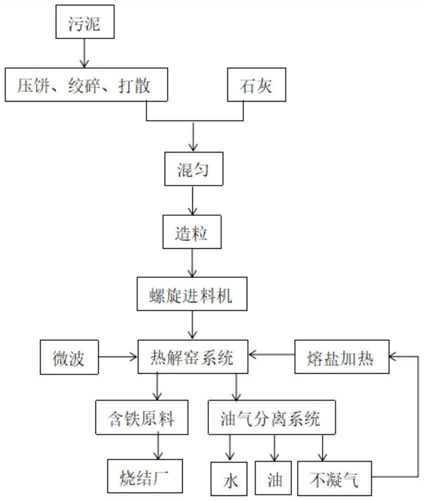
[0109] The oil-containing mud was added to the storage bin, and 6% lime was mixed after the strand, mix well, granulated.

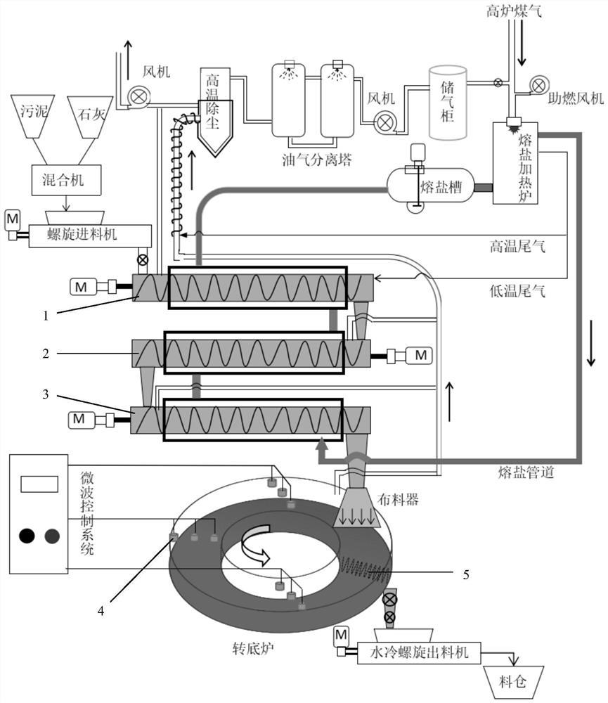
[0110] Start the molten salt heating system and pyrolysis flue gas treatment system, liquid molten salt in the spiral heating kiln jacket flows for 5-10 min, then start the spiral feeder and the migrant of each spiral kiln, and increase the melting salt heating furnace The blast furnace gas volume allows the exit molten salt temperature of the molten salt heating furnace to 500 ° C.

[0111] Start the turbine rotary trolley and microwave heating electronics control system, and oil-containing mud is p...

Embodiment 2

[0119] In this example, the steel plant is hot-rolled as an example, and its physical properties are shown in Table 1.

[0120] The oil-containing mud was added to the storage bin, and 5% lime was blended after the strand, mix well, granulated.

[0121] Start the molten salt heating system and pyrolysis flue gas treatment system, liquid molten salt in the spiral heating kiln jacket flows for 5-10 min, then start the spiral feeder and the migrant of each spiral kiln, and increase the melting salt heating furnace The blast furnace gas volume allows the exit molten salt temperature of the molten salt heating furnace to 500 ° C.

[0122] Start the bottom furnace rotary trolley and microwave heating electric control system, the oil-containing mud is preheated by the first paragraph to the third spiral kiln, and the temperature of the sludge reaches 380 ° C into the microwave turning bottom.

[0123] The power of the rotational speed and microwave of the rotary trolley is controlled, so...

Embodiment 3

[0131] In this example, the steel plant is hot-rolled as an example, and its physical properties are shown in Table 1.

[0132] The oil-containing mud was added to the storage bin, and 4% lime was mixed after the strand, mix well, granulated. Start the molten salt heating system and pyrolysis flue gas treatment system, liquid molten salt in the spiral heating kiln jacket flows for 5-10 min, then start the spiral feeder and the migrant of each spiral kiln, and increase the melting salt heating furnace The blast furnace gas volume allows the exit molten salt temperature of the molten salt heating furnace to 500 ° C.

[0133] Start the bottom furnace rotary trolley and microwave heating electric control system, the oil-containing mud is preheated by the first paragraph to the third spiral kiln, and the temperature of the sludge reaches 400 ° C and enters the microwave turning bottom, control the bottom The speed of rotational speed and microwave of the furnace rotates, so that the sl...


PUM


Abstract

The invention discloses a method and a device for recycling oily sludge of an iron and steel plant, and belongs to the field of sludge treatment. The method comprises the following steps of: loading oily sludge into a stock bin, pressing the oily sludge into cakes, mincing the cakes, scattering, adding lime in proportion, mixing well, and granulating the mixture; carrying out sludge particle heating, preheating dehydration and grease decomposition in a high-temperature fused salt external heating mode; feeding the sludge particles into a rotary hearth furnace, and further deeply pyrolyzing the sludge particles under an anaerobic condition and under the action of a microwave field; after the sludge material in the product stock bin is cooled, conveying the sludge material to a sintering plant; in the sintering plant, recycling the pyrolyzed sludge material as a sintering raw material, adding the pyrolyzed sludge material into a sintering proportioning bin, and blending the pyrolyzed sludge material into uniformly mixed ore according to the proportion required by the production process; and correspondingly reducing the dosage of the flux according to the alkalinity requirement of the sintered ore, and performing uniform mixing and sintering to produce sintered ore. Therefore, the oily sludge of the iron and steel plant is harmlessly treated, the treatment efficiency of the oily sludge and the energy utilization efficiency are improved, and the oily and ferric oxide-containing sludge is recycled.

Description

Technical field [0001] The present invention belongs to the field of sludge, and more particularly to a method and apparatus for treatment and resource utilization of steel mills, iron oxide sludge. Background technique [0002] At present, there are more than 1 million tons of oil-filled in China, and the sludge produced by the steel industry accounts for more than 30%. [0003] In order to eliminate the contact heat generated between the coil and the cast roller, the steel enterprise is used to cool and lubricate the emulsion or special oil during the modification of the steel blank and the rolls during the rolling steel, and the emulsion or special oil is required to produce grease and iron oxide. Waste, including oil-containing iron oxide, and oil-containing. These waste needs to be dealt with to fill or recycle. [0004] At present, there are preferred oil-free sludge disposal processes at home and abroad mainly chemically hot washing and pyrolysis. [0005] The chemical hot...

Claims


Application Information

Patent Timeline
IPC IPC(8): C02F11/10C02F11/00C02F11/13C10B53/00C02F103/16C02F101/30
CPCC02F11/10C02F11/00C02F11/13C10B53/00C02F2103/16C02F2101/30Y02W10/40
Inventor 徐万仁李建毛晓明陈小龙
Owner BAOSHAN IRON & STEEL CO LTD
Why Eureka
Try Eureka