Erbium-doped laser ultrashort pulse generation device and method
A technology of ultra-short pulse and generating device, which is applied in lasers, laser components, phonon exciters, etc., can solve the problems of narrow gain bandwidth of erbium-doped laser materials, lack of saturable absorbing devices, and difference in laser research progress, etc., to achieve Increased laser operation efficiency, good beam quality, and high laser conversion efficiency
- Summary
- Abstract
- Description
- Claims
- Application Information
AI Technical Summary
Problems solved by technology
Method used
Image
Examples
Embodiment 1
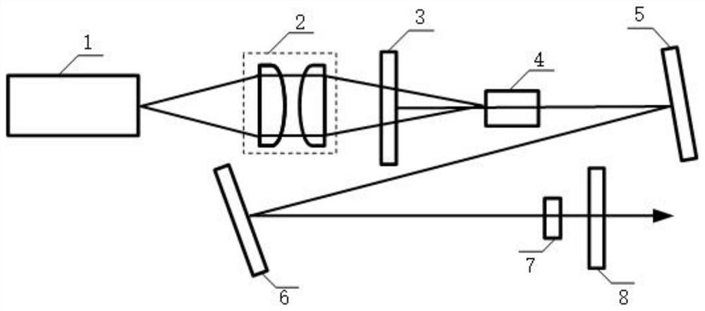
[0021] Such as figure 1 As shown, the above-mentioned laser resonant cavity is composed of a laser input mirror 3, a resonant cavity reflector 5, a resonant cavity reflector 6 and a laser output mirror 8. Laser high reflection film with high transmittance and wavelength of 1.6-1.7μm is placed at right angles to the optical path as shown in the figure. Resonant cavity mirror 5 and resonant cavity mirror 6 are flat concave mirrors with a radius of curvature of 100mm, coated with Reflective film, the angle with the light path is less than 5°, the laser output mirror 8 is a flat mirror, the laser output transmittance is 0.5% and 2%, the laser cavity length is 1.9 meters; the pump light passes through the coupling unit, and the pump light that is continuously running The pump light energy is focused into the gain matrix, and the gain medium is affected by the resonant cavity to generate positive feedback. The strong light pulse is amplified by passing through the saturable absorber...
Embodiment 2
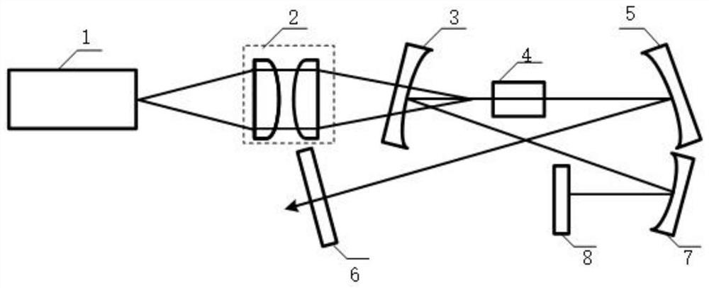
[0026] Such as figure 2 As shown, the above-mentioned laser resonator is composed of laser input mirror 3, resonator mirror 5, laser output mirror 6, resonator mirror 7 and reflective saturable absorber mirror 8, and the length of the laser cavity is 1.7 meters. The laser input mirror 3 is a plano-concave mirror with a radius of curvature of 100 mm, coated with a high-transmittance and high-reflection film for laser light, and placed at a small angle with the laser light path as shown in the figure, and the resonant cavity reflector 5 is a plano-concave mirror , the radius of curvature is 300mm, coated with laser high reflection film, the angle with the optical path is less than 5°, the laser output mirror 6 is a plane mirror, the laser output transmittance is 0.5% and 2%, the laser reflector 7 is a plano-concave mirror, The radius of curvature is 100mm, and the included angle with the optical path is less than 5°. In this example, the reflective saturable absorbing mirror 8 ...
Embodiment 3
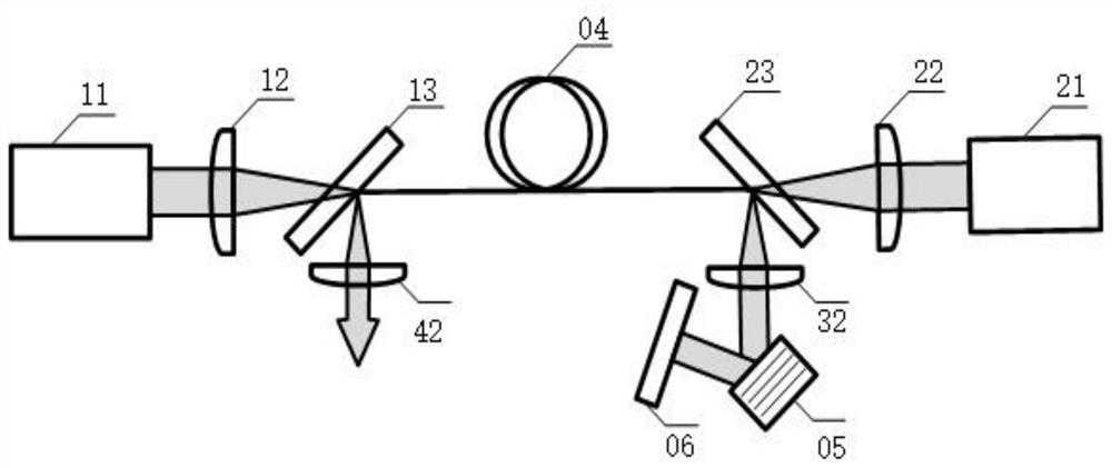
[0032] The schematic diagram of the structure of the optical fiber pump source 1 described in the embodiment of the present invention is as follows image 3 shown. The above-mentioned fiber laser pumping source 1 is a narrow linewidth erbium-ytterbium co-doped fiber laser with tunable wavelength and power, consisting of a first semiconductor pumping source 11, a first pumping focusing lens 12, a first dichroic mirror 13; Pump source 21, second pump focusing lens 22, second dichroic mirror 23; erbium-ytterbium co-doped fiber 04, first laser collimator lens 32, second laser collimator lens 42, reflective volume Bragg grating 05 and broadband Mirror 06 composition. The first semiconductor pumping source 11 is a semiconductor laser with continuous output, the maximum laser power is 40W, the center wavelength is 975nm, and the spectral width is about 3nm; the first pumping focusing lens 12 and the second pumping focusing lens 22 It is a plano-convex lens with a focal length of 30...
PUM
| Property | Measurement | Unit |
|---|---|---|
| Line width | aaaaa | aaaaa |
| Length | aaaaa | aaaaa |
| Diameter | aaaaa | aaaaa |
Abstract
Description
Claims
Application Information
 - R&D
- Intellectual Property
- Life Sciences
- Materials
- Tech Scout
- Unparalleled Data Quality
- Higher Quality Content
- 60% Fewer Hallucinations
Browse by: Latest US Patents, China's latest patents, Technical Efficacy Thesaurus, Application Domain, Technology Topic, Popular Technical Reports.
© 2025 PatSnap. All rights reserved.Legal|Privacy policy|Modern Slavery Act Transparency Statement|Sitemap|About US| Contact US: help@patsnap.com


