Method for treating radioactive waste liquid containing nitric acid through electrolytic tank

A technology of radioactive waste liquid and electrolytic cell, which is applied in the field of nuclear chemical industry, can solve problems such as difficult operation, difficult adjustment of formaldehyde, and treatment of radioactive gas, so as to achieve the effects of improving current efficiency, ensuring reduction potential, and controllable reaction process

Pending Publication Date: 2022-01-14
CHINA INSTITUTE OF ATOMIC ENERGY
View PDF10 Cites 0 Cited by
  • Summary
  • Abstract
  • Description
  • Claims
  • Application Information

AI Technical Summary

Problems solved by technology

However, the disadvantages of using formaldehyde and formic acid to carry out waste liquid destocking are: 1. The consumption of reagents is large, and a large amount of radioactive gases are generated in the reaction process and need to be treated.
Moreover, as the denitrification reaction proceeds, the concentration of nitric acid in the solution will continue to change, so it is difficult to continuously adjust the amount of formaldehyde during the reaction.
③The denitrification reaction temperature of formaldehyde (formic acid) needs to be controlled around 90°C, but at this temperature, zirconium and molybdenum in the high-level radioactive waste liquid will form precipitates, making operation difficult
As the concentration of nitric acid gradually decreases, the cathode polarization potential increases, and the hydrogen evolution reaction will become the main electrode reaction of the cathode. After the concentration of nitric acid in the solution is reduced to a certain level (about 2-3mol / L), the concentration of nitric acid will decrease when electrolysis continues. remain unchanged, therefore, in general, continuing to use electrolysis will not be able to further remove nitric acid
[0004] At present, research on electrolytic denitrification mainly focuses on the treatment of low-concentration nitrate pollution in aqueous solutions. A large number of researches focus on electrode materials loaded with different metal catalysts. Combining electrochemistry and chemical catalysis to improve current efficiency, but such methods cannot be used Removal of Nitric Acid in High Concentration Nitric Acid Solution

Method used


Image

  • Method for treating radioactive waste liquid containing nitric acid through electrolytic tank
  • Method for treating radioactive waste liquid containing nitric acid through electrolytic tank
  • Method for treating radioactive waste liquid containing nitric acid through electrolytic tank

Examples


Embodiment 1

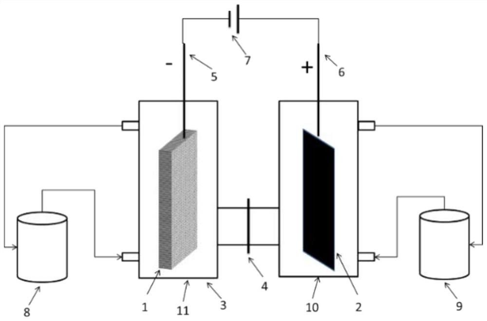
[0048] Electrolytic denitrification device such as figure 1 As shown, the DC power supply provides the current and voltage required for the electrolysis reaction.

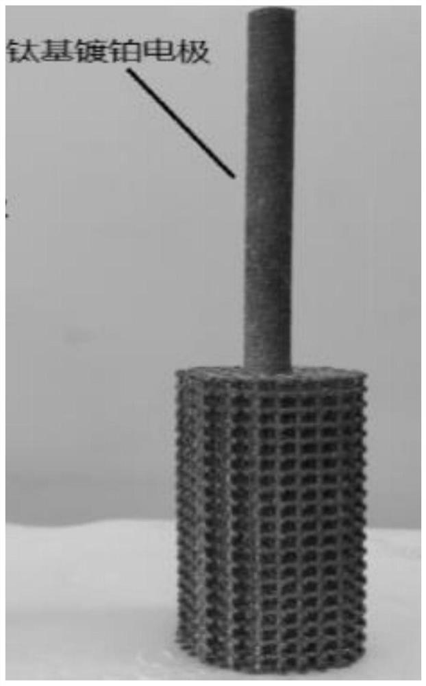
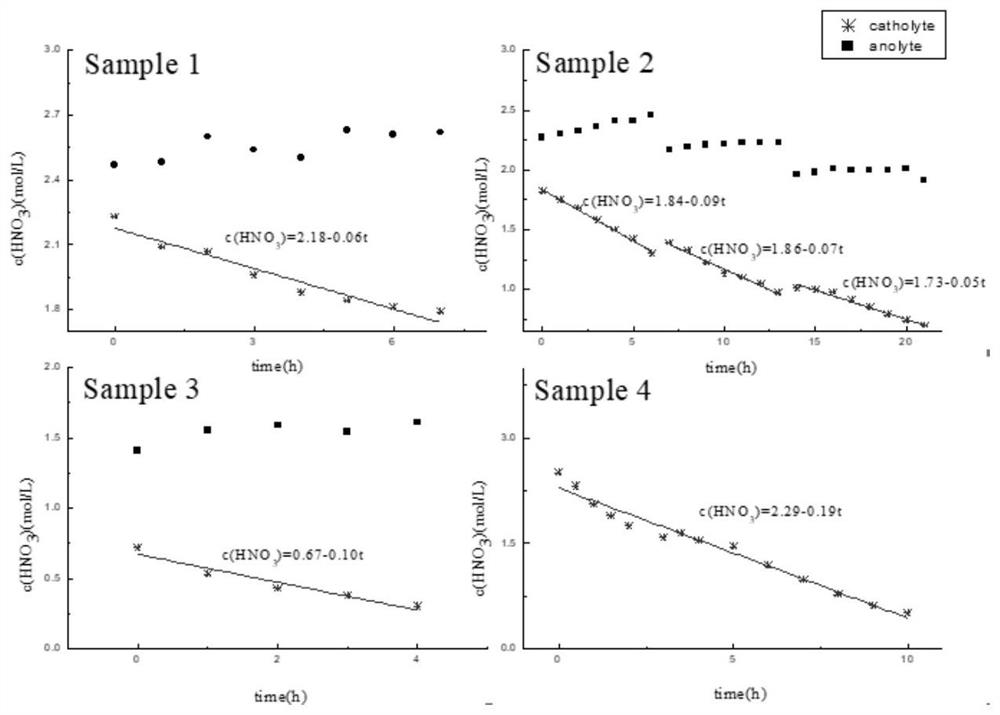
[0049] Inject 200mL, 2.47mol / L nitric acid solution into the anode area solution storage tank 9, simulate high-level radioactive waste liquid of 2.23mol / L nitric acid concentration of 200mL (containing 100mg / L uranium, 500mg / L zirconium, 200mg / L molybdenum, 200mg / L ruthenium, 300mg / L iron, 100mg / L cesium, 100mg / L barium, the same below) are injected into the solution storage tank 8 in the cathode area. Add a 50mm×100mm platinum mesh as the anode, 50mm×5mm×100mm 3D printed porous titanium (porosity 72%, pore diameter 2mm) as the cathode in the above electrolytic denitrification device, and use Nafion117 proton exchange membrane between the anode area and the cathode area As a diaphragm material; pass through a constant current of 3.0A for 7 hours, and measure the change curve of the concentration of nitric acid in ...

Embodiment 2

[0051] The difference between this embodiment and Example 1 is that the liquid in the anode region is a mixed solution of 2.27mol / L nitric acid and 0.5mol / L hydrazine nitrate solution of 200mL, and the liquid in the cathode region is 1.82mol / L nitric acid concentration of 200mL The simulated high-level radioactive waste liquid, constant current 3.0A, intermittent electrolysis, electrolysis time a total of 21h. During the electrolysis process, the solution in the nitric acid storage tank was regularly sampled, the concentration of nitric acid was analyzed, and the denitrification rate of nitric acid was calculated based on the change of the total volume of the solution. The results are shown in Table 1.

Embodiment 3

[0053] The difference between this embodiment and Example 1 is that the liquid in the anode region is a mixed solution of 200mL of 1.41mol / L nitric acid and 0.50mol / L hydrazine nitrate, and the liquid in the cathode region is 200mL of 0.72mol / L nitric acid concentration. Simulate high-level waste liquid, constant current 3.0A, electrolysis time 4h. During the electrolysis process, the solution in the nitric acid storage tank was regularly sampled, the concentration of nitric acid was analyzed, and the denitrification rate of nitric acid was calculated based on the change of the total volume of the solution. The results are shown in Table 1.


PUM

PropertyMeasurementUnit
pore sizeaaaaaaaaaa
porosityaaaaaaaaaa
porosityaaaaaaaaaa

Abstract

The invention relates to a method for treating radioactive waste liquid containing nitric acid through an electrolytic tank, wherein the electrolytic tank comprises a cathode region and an anode region, a diaphragm is arranged between the cathode region and the anode region, the material of a cathode in the cathode region is made of a titanium metal material with a through hole, and an anode in the anode region is made of a platinum metal material or a carbon material. The method comprises the steps: introducing the radioactive waste liquid containing nitric acid into the cathode region, and maintaining a flowing state in the cathode region, so as to electrolyze the radioactive waste liquid containing nitric acid when flowing through the through hole.

Description

technical field [0001] The disclosure relates to the field of nuclear chemical industry, in particular to a method for treating radioactive waste liquid containing nitric acid through an electrolytic cell. Background technique [0002] In the process of extracting and purifying uranium, plutonium, neptunium and other radioactive isotopes from spent fuel elements, a large amount of water, steam, chemical reagents and extraction agents are used, resulting in a large amount of radioactive waste liquid. According to the difference in radioactivity level, radioactive waste liquid can be divided into high-level waste liquid and medium-level and low-level waste liquid. In order to facilitate storage or subsequent treatment, the primary problem in the treatment of radioactive waste liquid is volume reduction, and evaporation and concentration are generally used. However, due to the high concentration of nitric acid in the waste liquid, the concentration ratio of the waste liquid is...

Claims


Application Information

Patent Timeline
Patent Type & Authority Applications(China)
IPC IPC(8): C02F1/461G21F9/06G21F9/20C02F101/16
CPCG21F9/20G21F9/06C02F1/461C02F1/46109C02F2201/46115C02F2001/46161C02F2101/16C02F2201/46185
Inventor 张虎欧阳应根赵晶
Owner CHINA INSTITUTE OF ATOMIC ENERGY
Why Eureka
Try Eureka