Indium phosphide quantum dot electroluminescent device based on tin oxide as electron injection layer and preparation of indium phosphide quantum dot electroluminescent device

A technology of electroluminescent devices and electron injection layers, which is applied in the fields of electric solid-state devices, semiconductor/solid-state device manufacturing, electrical components, etc., can solve the problems of InP quantum dot light-emitting diode device structure adjustment and optimization research, and achieve an improvement The effect of electroluminescent efficiency, enhanced electron transmission, and reduced turn-on voltage

Pending Publication Date: 2022-03-25
SOUTH CHINA UNIV OF TECH
View PDF0 Cites 0 Cited by
  • Summary
  • Abstract
  • Description
  • Claims
  • Application Information

AI Technical Summary

Problems solved by technology

There are few studies on device structure adjustment and optimization of InP quantum dot light-emitting diodes

Method used


Image

  • Indium phosphide quantum dot electroluminescent device based on tin oxide as electron injection layer and preparation of indium phosphide quantum dot electroluminescent device
  • Indium phosphide quantum dot electroluminescent device based on tin oxide as electron injection layer and preparation of indium phosphide quantum dot electroluminescent device
  • Indium phosphide quantum dot electroluminescent device based on tin oxide as electron injection layer and preparation of indium phosphide quantum dot electroluminescent device

Examples


Embodiment 1

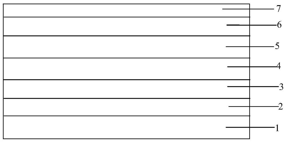
[0031] select figure 1 The device structure shown above uses an ITO substrate and ultrasonically cleans it with lotion, deionized water, and isopropanol for 10 minutes to remove surface pollutants. After drying with high-pressure nitrogen, use oxygen plasma to modify the surface, and then Spin-coat tin dioxide (particle size about 3-5nm) in the glove box as the electron injection layer (thickness ~40nm), the solvent used is ethanol; then spin-coat zinc and magnesium oxide on the tin dioxide as the electron transport layer (thickness ~50nm ), the solvent used is ethanol, and the green light indium phosphide quantum dot material is spin-coated on the zinc magnesium oxide to prepare the quantum dot light-emitting layer (the green light InP / ZnS quantum dot of the core-shell structure), and the solvent used is n-octane (thickness ~ 30nm) , and finally in the high vacuum evaporation chamber (3×10 -4 Pa) The hole transport layer 4,4',4"-tris(carbazol-9-yl)triphenylamine (thickness ~...

Embodiment 2

[0034] select figure 1 The device structure shown in the figure uses an ITO substrate, which is ultrasonically cleaned with lotion, deionized water, and isopropanol for 10 minutes to remove surface pollutants. After drying with high-pressure nitrogen, it is surface-modified with oxygen plasma, and then sprayed The method is to spray tin dioxide on the ITO as an electron injection layer (thickness ~ 40nm), the solvent used is ethanol, then transfer the substrate to a nitrogen glove box, and then spin-coat zinc and magnesium oxide on the tin dioxide as an electron transport layer (thickness~50nm), the solvent used is ethanol, spin-coats green light indium phosphide quantum dot material on zinc magnesium oxide to prepare quantum dot luminescent layer, used solvent is n-octane (thickness~30nm), finally in high vacuum evaporation chamber ( 3×10 -4 Pa) The hole transport layer 4,4',4"-tris(carbazol-9-yl)triphenylamine (thickness ~50nm), the hole injection layer MoO x (thickness ~ ...


PUM

PropertyMeasurementUnit
particle diameteraaaaaaaaaa
thicknessaaaaaaaaaa
thicknessaaaaaaaaaa

Abstract

The invention belongs to the technical field of electroluminescent devices, and discloses an indium phosphide quantum dot electroluminescent device based on tin oxide as an electron injection layer and preparation of the indium phosphide quantum dot electroluminescent device. The indium phosphide quantum dot electroluminescent device comprises an ITO substrate, an electron injection layer, an electron transport layer, an indium phosphide quantum dot luminescent layer, a hole transport layer, a hole injection layer and a metal anode which are stacked in sequence. And the electron injection layer is tin dioxide. The tin dioxide material is used as the electron injection layer of the electroluminescent device, electron injection is optimized, the indium phosphide quantum dot electroluminescent device based on the tin dioxide material as the electron injection layer is prepared by using the high electron mobility of the tin dioxide material, the turn-on voltage of the quantum dot device is reduced, and the light emitting efficiency of the device is improved. The electroluminescent efficiency is improved, the working life is prolonged, and the application of the quantum dot material in the field of next-generation display and illumination is promoted.

Description

technical field [0001] The invention belongs to the technical field of indium phosphide quantum dot photoelectric devices, and relates to an indium phosphide quantum dot electroluminescent device based on tin dioxide as an electron injection layer, in particular to an indium phosphide quantum dot electroluminescent device and its preparation method. Background technique [0002] In the field of optoelectronic display, quantum dot display has attracted the attention of scientists due to its wide spectral tunability, narrow full width at half maximum (FWHM), high color purity and other excellent performance, and is considered to be the next generation An extremely prominent candidate for display technology. The performance of quantum dots light emitting diode (QLED) has been developed rapidly, especially the red, green and blue luminous performance of cadmium-based QLED is very close to that of organic light emitting diode (OLED). Level. However, cadmium element has serious...

Claims


Application Information

Patent Timeline
Patent Type & Authority Applications(China)
IPC IPC(8): H01L51/54H01L51/50H01L51/56
CPCH10K50/115H10K50/171H10K2102/00H10K71/00
Inventor 许伟彭俊彪宁洪龙姚日晖
Owner SOUTH CHINA UNIV OF TECH
Why Eureka
Try Eureka