

Red light emitting fluorescent dye, synthesizing process and use thereof
A fluorescent dye and red light technology, applied in the field of fluorescent dye synthesis, can solve the problems of high price, low yield, complex synthesis method, etc., and achieve the effect of separation and purification
- Summary
- Abstract
- Description
- Claims
- Application Information
AI Technical Summary
Problems solved by technology
Method used
Image

Examples
Embodiment 1
[0057] Example 1: Synthesis of asymmetric pyrones with the above P14 structure:
[0058]
[0059] Add 200ml of anhydrous ethylene glycol dimethyl ether in a 1000ml three-necked flask equipped with a constant pressure dropping funnel and an airway tube, protect with nitrogen, add 18 grams of sodium hydride (60%, 0.45mol), and heat Reflux, slowly add 100ml of ethylene glycol dimethyl ether solution of 0.15mol acetylacetone (1) dropwise under constant stirring, after 40 minutes after the addition is complete, heat and stir for 40 minutes, then add 0.15mol tert-butyl Quickly pour 100 ml of ethylene glycol dimethyl ether solution of methyl ethyl ester (2) into the reaction flask, the whole process should not exceed 2 minutes, and then reflux the reaction solution for 4 to 8 hours. Then evaporate most of the ethylene glycol dimethyl ether solvent under reduced pressure, add 150ml of ether to the obtained paste under ice-water cooling, stir for 10 minutes, and drop 200ml of cold w...
Embodiment 2
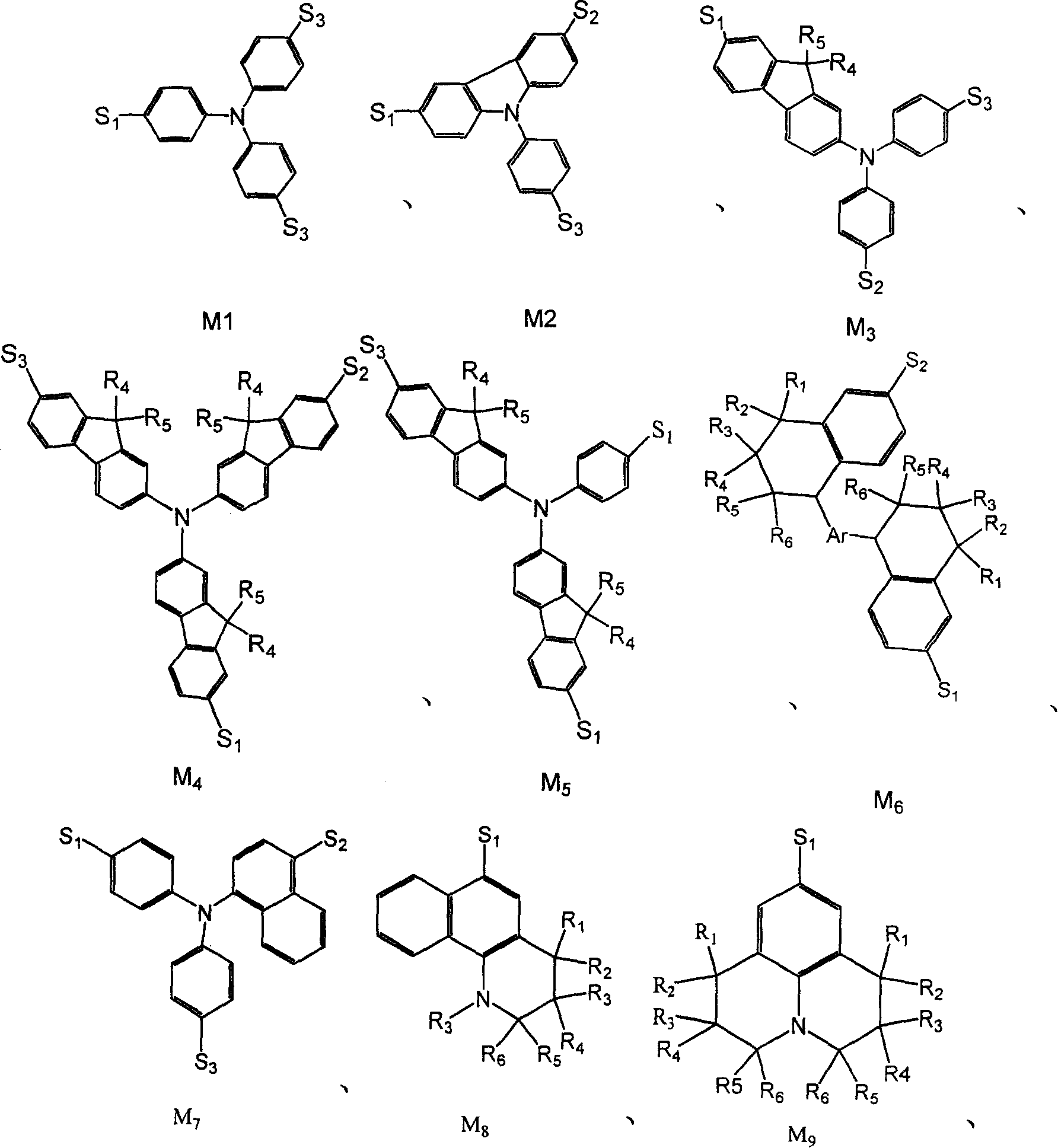
[0070] Embodiment 2: having the general formula M 1 Synthesis of the structure of Y1
[0071]
[0072] In a round bottom flask was added 4-(1,3-indanedione)-2-methyl-6-tert-butyl-pyran (structure A 1 ) 1mmol, N, N-bis-(4-formylphenyl) aniline (structure D 101 ) 1mmol, 30ml acetonitrile, 0.40ml hexahydropyridine, heated to reflux for 24 hours. Cool, filter the reaction solution, and wash the solid with ethanol for several times, and wash it with DMF / CHCl 3 The mixed solution was recrystallized to obtain product Y1 with a yield of 74%.
[0073] Elemental analysis Calculated value (C 38 h 31 NO 3 ): C, 83.03; H, 5.68; N, 2.55;
[0074] Measured value: C, 83.04; H, 5.68; N, 2.54;
[0075] Mass spectrometry (MS + ): 549 (M + )
Embodiment 3
[0076] Embodiment 3: having the general formula M 7 Synthesis of the structure of Y2
[0077]
[0078] In a round bottom flask was added 4-(1,3-indanedione)-2-methyl-6-tert-butyl-pyran (structure A 1 )1mmol, D 122 1.2mmol, 35ml acetonitrile, 0.50ml hexahydropyridine, heated to reflux for 24 hours. Aftertreatment method is the same as embodiment 2, product Y 2 , yield 74%.
[0079] Elemental analysis Calculated value (C 42 h 33 NO 3 ): C, 84.11; H, 5.55; N, 2.34;
[0080] Measured value: C, 84.10; H, 5.57; N, 2.35;
[0081] Mass spectrometry (MS + ): 599 (M + ).
PUM
| Property | Measurement | Unit |
|---|---|---|
| Lumen efficiency | aaaaa | aaaaa |
| Lumen efficiency | aaaaa | aaaaa |
| Lumen efficiency | aaaaa | aaaaa |
Abstract
Description
Claims
Application Information