Biomass, especially active sludge chain dry pyrolytic oil maker and system
An activated sludge and biomass technology, applied in the fields of renewable resources and environmental protection, energy and chemical industry, can solve the problems of product quality and recovery rate, such as violent reaction, insufficient pyrolysis, serious secondary reaction, etc.
- Summary
- Abstract
- Description
- Claims
- Application Information
AI Technical Summary
Problems solved by technology
Method used
Image
Examples
Embodiment 3
[0079] In Figures 5 and 7, an embodiment 3 of the present invention used as a dryer is shown;
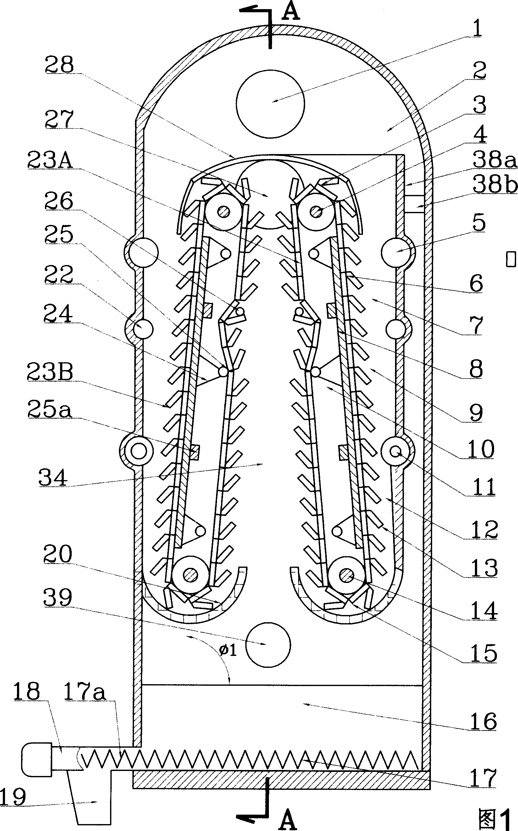
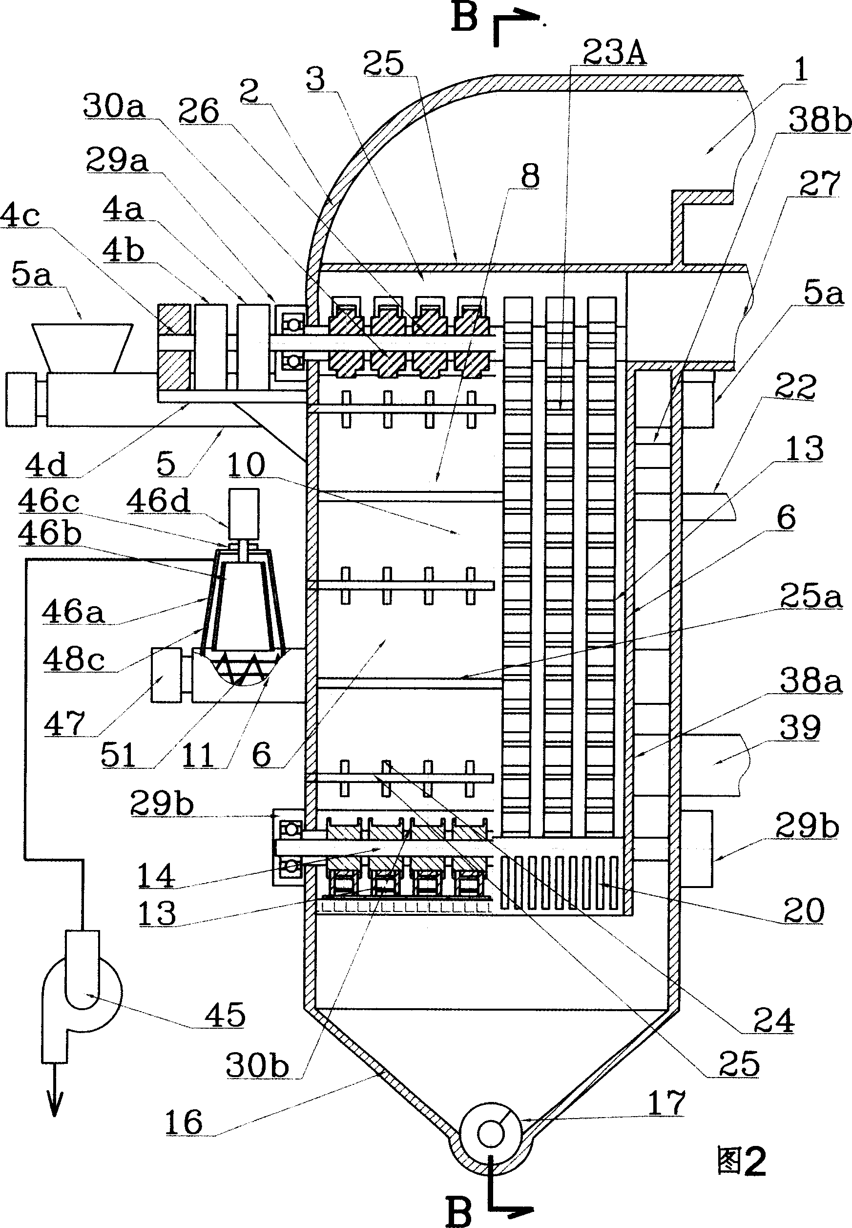
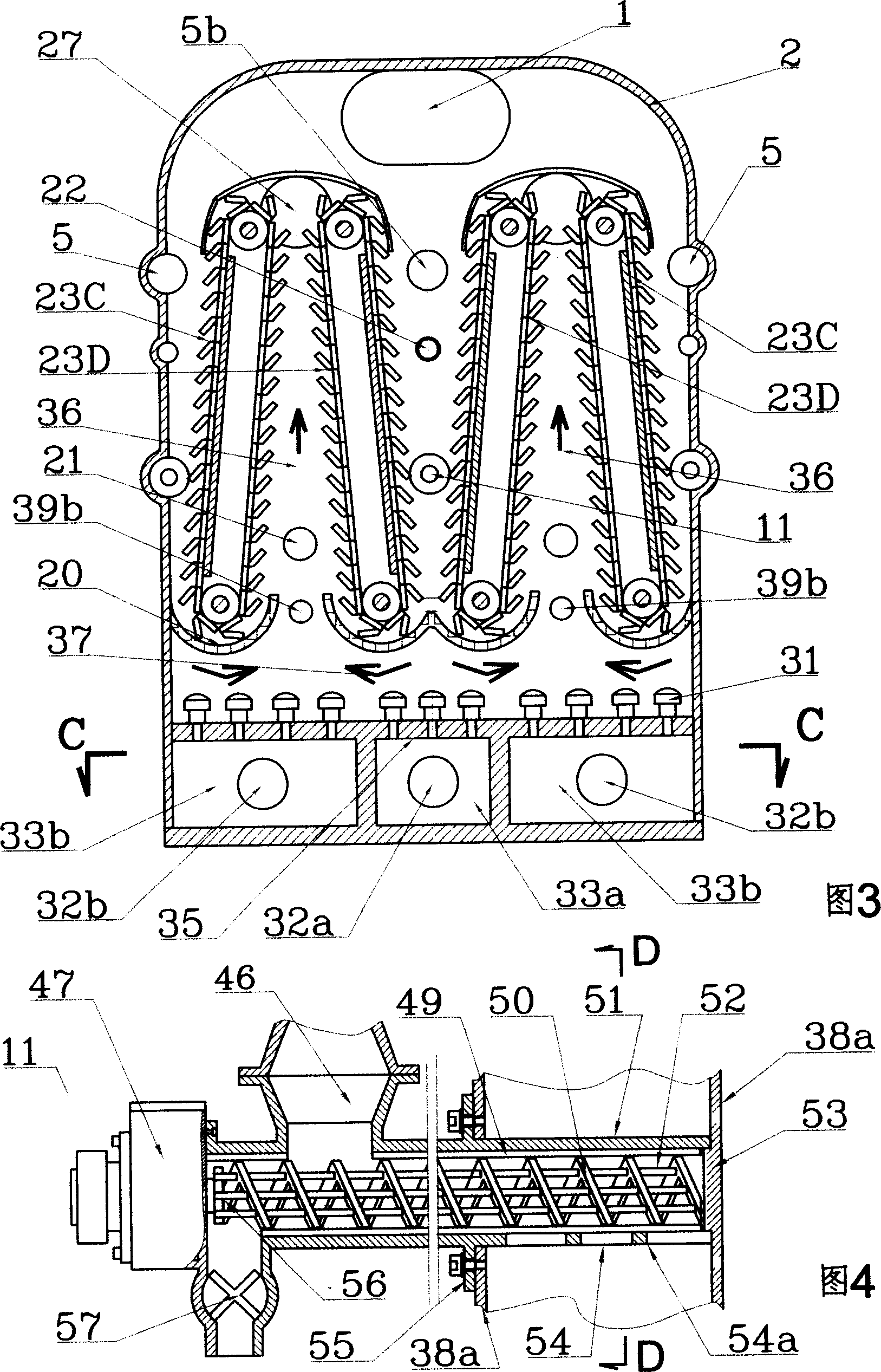
[0080] The feature of this embodiment is that two groups of chain heat exchangers are formed into a pair of symmetrically inclined chain heat exchangers 23A and 23B, and two pairs of chain heat exchangers 23C, 23D and 23E are arranged in the housing 2, and two of them A heating passage 38 is arranged between the adjacent downlinks of the chain heat exchanger, and a burner 39 of fluid fuel is arranged on the top wall of the heating passage 38, and the flame injection position of the burner 39 is heated on the downlink side. Plate 38a, the high-temperature gas 37 passes through the turning chain 15 at the lower end of the uplink, and then turns from the top of the constant temperature space through the downlink to enter the channel between the heating wall plate 38a and the vertical wall of the housing, and from the waste gas discharge port at the bottom of the channel 1a is discharge...
Embodiment 5
[0083] In Figures 9, 14 and 15, the present invention is shown as an embodiment 5 in which drying is the main method and pyrolysis is the auxiliary method;
[0084] Among the three groups of chain heat exchangers set in the constant temperature space, two groups of chain heat exchangers 23A, 23B form a pair of symmetrically inclined chain heat exchangers, and the downlink of the pair of chain heat exchangers 23B The chain cables of the chain path are adjacent to the uplink path of another group of chain path heat exchangers 23E, and the chain paths of the chain path heat exchangers 23E are arranged in the chain path formed by their own chain cable partition screen 8 and the heating vertical wall 38a In 40, each chain cable of each group of chain heat exchangers moves in parallel through the uplink, downlink, and the steering chain formed by the driving sprocket and the driven sprocket and then closed. A burner 39 of fluid fuel is arranged on the top wall of the heating channel...
Embodiment 6
[0087] In Figure 10, the present invention is shown as an embodiment 6 in which drying is the main method and pyrolysis is the auxiliary method;
[0088] The feature of this embodiment is that two sets of chain heat exchangers are formed into a pair of symmetrically inclined chain heat exchangers 23A and 23B, and three pairs of chain heat exchangers 23A, 23B and 23E are arranged in the housing 2, two of which A heating passage 38 is arranged between the adjacent downlinks of the group chain heat exchangers 23B and 23E, and a burner 39 of fluid fuel is arranged on the top wall of the heating passage 38, and the flame injection position of the burner 39 is in the downlink. The so-called heating wall plate 38a is heated by the side, and the high-temperature gas 37 passes through the uplink of the chain heat exchanger 23E, the turning chain 15 at the lower end, and then passes through the uplink of the chain heat exchanger 23B and 23A from the bypass exhaust port 27 is connected t...
PUM
 Abstract
Description
Claims
Application Information
 - R&D
- Intellectual Property
- Life Sciences
- Materials
- Tech Scout
- Unparalleled Data Quality
- Higher Quality Content
- 60% Fewer Hallucinations
Browse by: Latest US Patents, China's latest patents, Technical Efficacy Thesaurus, Application Domain, Technology Topic, Popular Technical Reports.
© 2025 PatSnap. All rights reserved.Legal|Privacy policy|Modern Slavery Act Transparency Statement|Sitemap|About US| Contact US: help@patsnap.com


