Artificial heart valve with scaffold

An artificial heart and valve technology, which is applied to heart valves, devices with human tubular structures, and medical science, can solve problems such as poor bending, valve leaflet wear, and high friction, and achieve more optimized structure and function, increased strength and Longevity and low friction effect

An artificial heart and valve technology, which is applied to heart valves, devices with human tubular structures, and medical science, can solve problems such as poor bending, valve leaflet wear, and high friction, and achieve more optimized structure and function, increased strength and Longevity and low friction effect

CN1961845AActive Publication Date: 2007-05-16BEIJING BALANCE MEDICAL

Image

  • Artificial heart valve with scaffold
  • Artificial heart valve with scaffold
  • Artificial heart valve with scaffold

Examples


Embodiment Construction

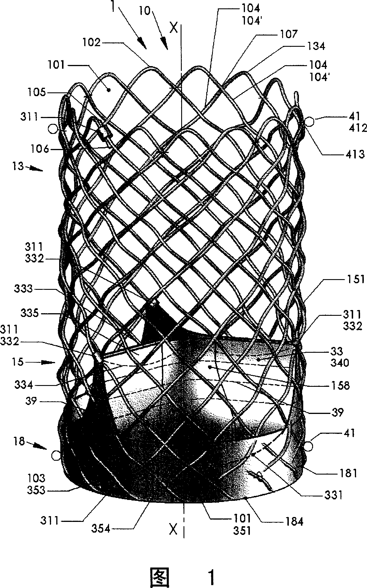
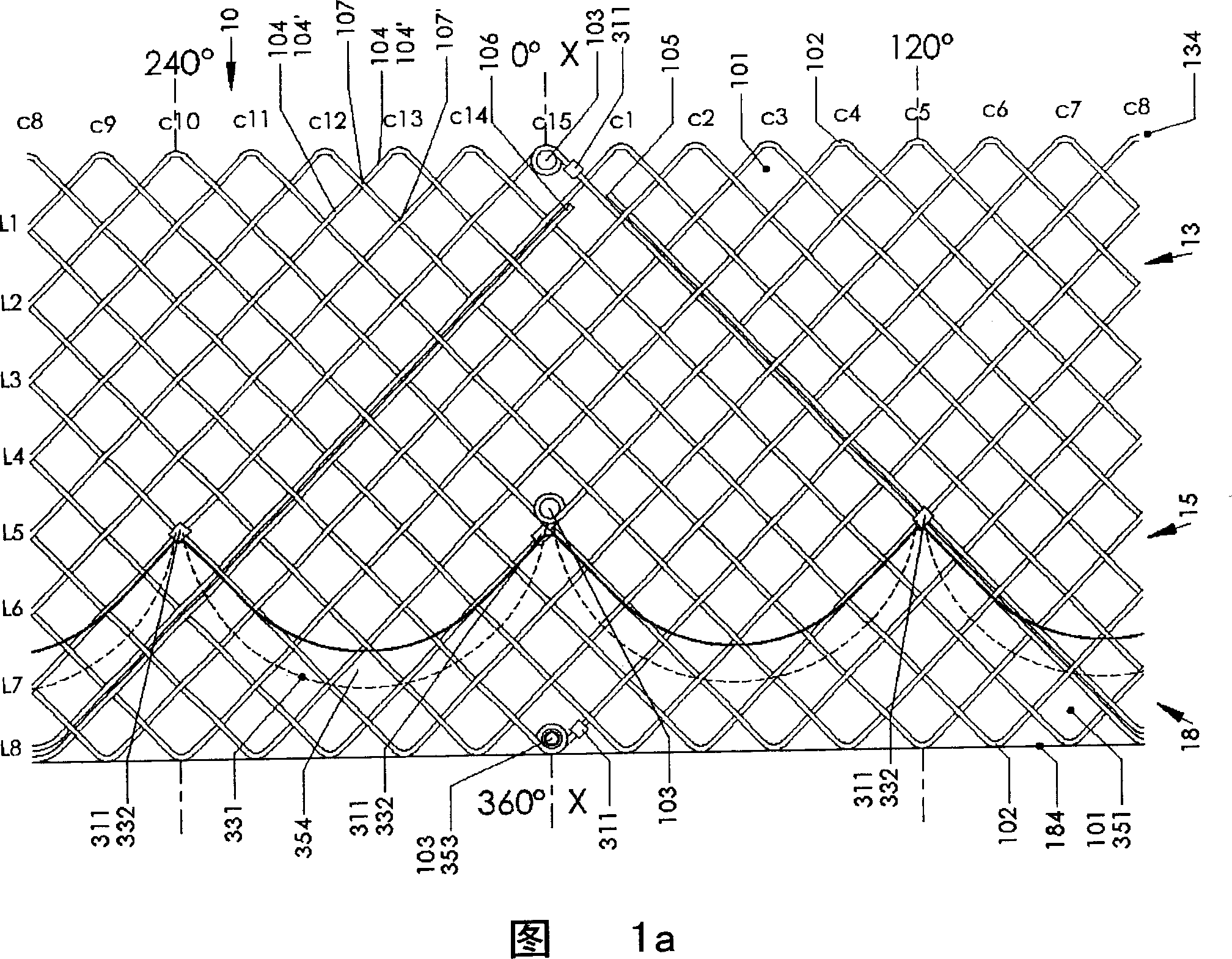
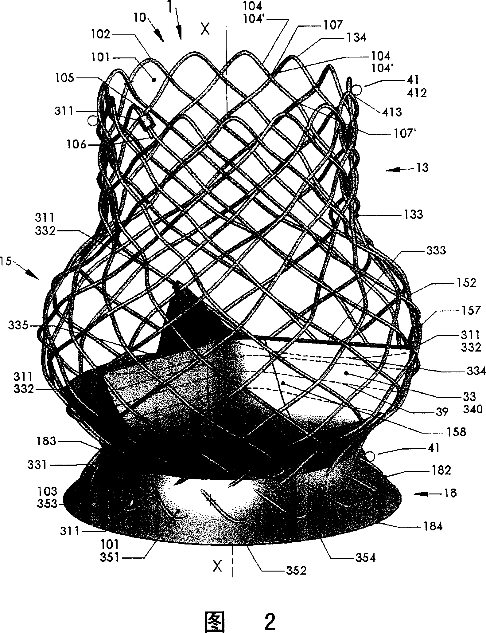
[0084] Referring to Fig. 1, referring to Fig. 2, Fig. 3, Fig. 4, Fig. 5, Fig. 6, and Fig. 10a, Fig. 10b, Fig. 10c, Fig. 10d, Fig. 10e, Fig. 10f, the artificial heart stent valve 1 of the present invention comprises: Radially deformable self-expanding mesh stent 10, X-ray-opaque markers 311, 312, valve leaflets 33 that can be switched and allow blood to pass through in one direction, sealing membranes 351, 354, sealing rings 37, reinforcing fibers in the synthetic membrane 39 and flexible coupling ring 41.

[0085] The valve leaflets 33, the sealing membranes 351, 354, and the sealing ring 37 can be made of biological materials or synthetic polymer materials. If it is made of biological materials, the valve leaflets 33, sealing membranes 351, 354 and sealing ring 37 are sutured on the stent 10; if it is made of synthetic polymer materials, the self-expanding stent valve 1 can form a seamless integrated whole, In this way, the strength of the stent valve 1 can be enhanced, and ...


PUM


Abstract

The invention relates to an artificial heart support valve, wherein it comprises tubular mesh support, valve blade, sealing film, impermeable x-ray mark, and flexible coiple ring; the middle part of mesh support is round or cylinder, or arranged with radial protrusion, or arranged with outer annular structure, or arranged with outer free tone, or arranged with radial protrusion and outer free tone. The invention can radial compress to transmit into accurate position via medium device, to be expanded, while the expanded valve will meet the shape of valve, without leakage. The invention can avoid being pushed when the blood refluxes and it is closed.

Description

technical field [0001] The invention relates to a substitute for human tissue, in particular to an artificial heart stent valve. Background technique [0002] The heart is the most important organ of the human body. The heart is divided into two parts, the left and the right, and each part includes the atrium and the ventricle. The left and right atria and right and left ventricles are separated by the atrial and ventricular septum, respectively. There are four heart valves in the heart, namely the tricuspid valve, pulmonary valve, mitral valve and aortic valve. In the human blood circulation mechanism, the four heart valves play a vital role. The hypoxic blood from the systemic circulation mechanism enters the right atrium through the vena cava, and then enters the right ventricle through the tricuspid valve. The contraction of the right ventricle pushes the blood into the pulmonary circulation mechanism through the pulmonary valve, and the oxygen-saturated blood returns ...

Claims


Application Information

Patent Timeline
16 May 2007
Publication
CN1961845A
IPC
A61F2/02; A61F2/06; A61F2/24
CPC
A61F2250/0098; A61F2/2418
Inventors
温宁