Integral fuel and heat sink refrigerant synthesis for prime movers and liquefiers

a technology of prime movers and liquefiers, which is applied in the field of renewable energy storage system, can solve the problems of high energy consumption, high cost, and inefficient other storage concepts under development, and achieve the effect of reducing fuel consumption and emissions, and reducing energy requirements

Active Publication Date: 2019-07-09
KAUFMAN JAY STEPHEN
View PDF7 Cites 1 Cited by
  • Summary
  • Abstract
  • Description
  • Claims
  • Application Information

AI Technical Summary

Benefits of technology

[0014]The object of the present invention is to provide local and highway liquid fuel and heat sink refrigerant stations for phase change energy storage by motor vehicle and distributed generatio...

Problems solved by technology

Moreover, the products of combustion are both unhealthy and dangerous for the environment, while the gradual increase in temperature of the earth's atmosphere, or “greenhouse effect”, advises development of energy technology that minimizes the release of heat and greenhouse gases.
Energy storage of solar, wind and other intermittent sources has, in general, been dominated by batteries, which are resource intensive to manufacture, have limited number of charge cycles and may present a fire hazard.
Other storage concepts under development are too expensive, hazardous or inefficient, including super capacitors, flywheels and compressed air.
Renewable fuels are useful for extended unavailability of intermittent energy sources, but are in limited use, including compressed hydrogen, liquid natural gas, and bio-fuels.
Hydrogen is produced inefficiently by electrolysis of water or steam reforming of methane from natural gas, which is available via the environmentally controversial fracking process.
Because hydrogen is burned in inefficient converters, on-board vehicle storage is problematic and high pressures must be employed.
Consumption of refrigerant is excessive in these high pressure engines (40 to 80 bar), which are not optimized for thermodynamic cycle or pressure ratio, nor supplemented by recovered energy.
While selection of these energy sources is based on availability and economics, inherent disadvantages include transmission loss, transport of the refrigerant and perpetuation of the environmental downside of centralized fossil fuel and nuclear use.
As expected, there are also issues with the use of renewables, primarily unavailability of solar, wind and geo-thermal, and inefficiency of energy conversion co...

Method used


Image

  • Integral fuel and heat sink refrigerant synthesis for prime movers and liquefiers
  • Integral fuel and heat sink refrigerant synthesis for prime movers and liquefiers
  • Integral fuel and heat sink refrigerant synthesis for prime movers and liquefiers

Examples


Embodiment Construction

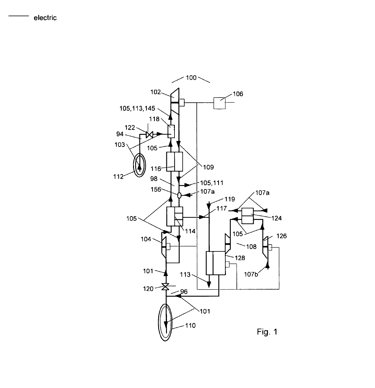
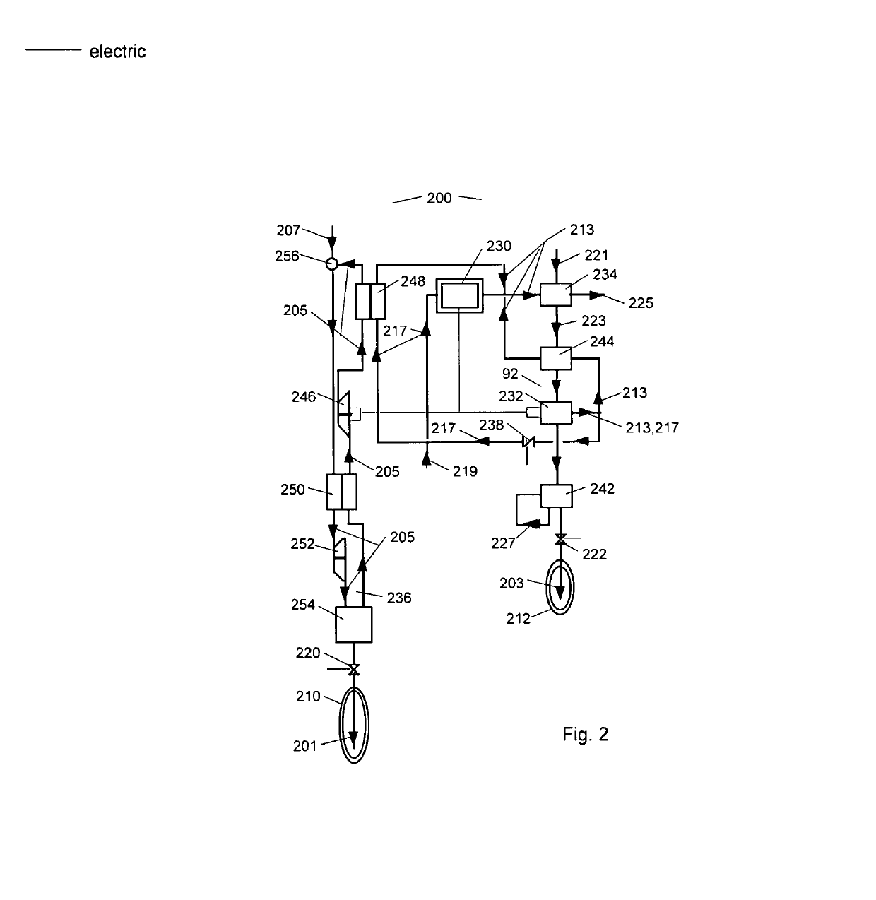
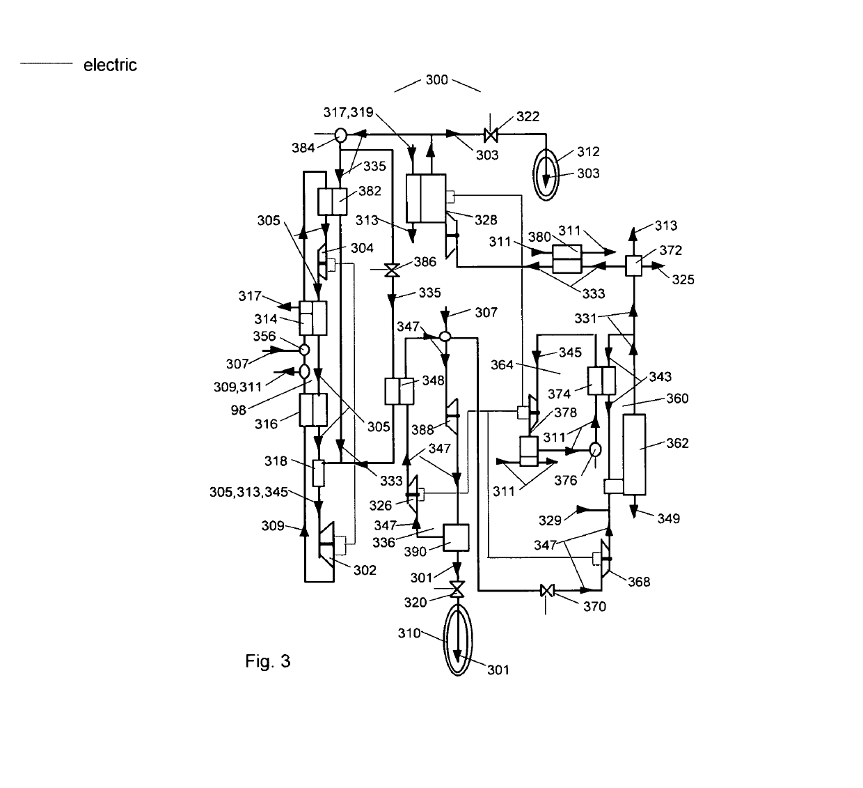
[0034]As a preface, it should be noted that all physical system components are referred to with an even reference number and all fluid compounds that move amongst the physical components are referred to with an odd reference number. Regardless of reference number, features with the same name are substantially the same features throughout the Figures. In addition, similar features that include reference numbers in some but not all Figures should be considered to be substantially similar features. Finally, it is noted that when a specific model or distributor of a system component is included, this inclusion is merely exemplary and comparable components may be substituted.

[0035]Referring first to FIG. 1, a schematic illustrating a preferred embodiment of a motor vehicle propulsion system 100 of the present invention is provided. Although the preferred use of system 100 is to propel a motor vehicle, one of ordinary skill in the art will recognize that it may be used to propel many type...


PUM


Abstract

A system for renewable energy storage, providing integral synthesis of heat source cryo-fuel and heat sink refrigerant for distributed electric generation and motor vehicle prime movers and refrigerant liquefiers. Fuel synthesis is by gasification and anaerobic digestion of organic feedstock with heat recovery to drive thermo-chemical reactor and air and fuel liquefiers.

Description

CLAIM OF PRIORITY[0001]This application is a continuation in part of and claims the benefit of priority of co-pending U.S. patent application Ser. No. 16 / 024,895, filed on Jul. 1, 2018.FIELD OF THE INVENTION[0002]The present invention relates to a system for renewable energy storage, and in particular to integral synthesis of heat source cryo-fuel and heat sink refrigerant for distributed generation and motor vehicle prime movers and liquefiers.BACKGROUND[0003]Since the 1970's a high efficiency prime mover with renewable energy storage has been a goal of motor vehicle and distributed electric generation design to provide energy independence, conserve fossil fuels, and reduce emission of combustion products. This has led to an increased need for clean and reliable energy storage devices, which can store the power generated from clean energy sources, and make it readily available when needed in a wide range of applications. As fossil fuels are consumed more rapidly than they can be pr...

Claims


Application Information

Patent Timeline
IPC IPC(8): B67D7/04F02C6/14F02C7/10F17C5/02F02C3/28F02C3/34F25J1/00
CPCB67D7/0498F02C6/14F02C3/34F02C7/10F02C3/28F17C5/02F17C2221/033F17C2221/031F25J2260/60F17C2270/0581F25J1/0012F25J1/0022F02C6/16F25J1/0035F25J1/004F25J1/0045F25J1/0202F25J1/0221F25J1/0225F25J1/0228F25J1/0236F25J1/0275F25J1/0282F25J1/0283F25J1/0284F25J2205/20F25J2210/66F25J2210/80F25J2220/66F25J2260/30F25J2270/908Y02E20/14Y02E20/16Y02E50/10Y02E60/16Y02E70/30F02C3/04
Inventor KAUFMAN, JAY STEPHEN
Owner KAUFMAN JAY STEPHEN
Why Eureka
Try Eureka