Separator for solid electrolyte condenser and solid electrolyte condenser using the same

Active Publication Date: 2002-08-29
NIPPON KODOSHI +1
View PDF2 Cites 17 Cited by
  • Summary
  • Abstract
  • Description
  • Claims
  • Application Information

AI Technical Summary

Problems solved by technology

However, a insulating oxide coat is damaged by the heating, thereby increasing a leak current.
Further, the condenser is short-circuited at a higher rate, even when the condenser is repaired by aging.
Further, the condenser of this type has a disadvantage that a highly oxidization resistive and costly silver plated lead wire must be used, because the plated layer such as tin/zinc layer of the conventional lead wire of the solid electrolyte condenser is oxidized by the heating, thereby reducing the wetting to a solder at a lead wire portion of the conventionally plated wire of a finished product.
The glass fiber nonwoven fabric electrolyte paper causes bad influences to working environments, due to scattering of the needle-like glass fibers during cutting and rolling them.
Further, a bending strength of the paper during rolling is not sufficient enough to prevent the short-circuit in the finished products.
Further, the glass fiber paper is thin and is difficult to be manufactured at a thickness of 40 to 50 .mu.m.
Even if a paper is manufactured at that thickness, the strength of the paper is so small that the paper can hardly be rolled.
Thus, the glass fiber paper is not suitable for manufacturing recent small-sized electronic parts.
Further, a tensile strength of the nonwoven fabric of resin by dry method such as the melt blow method, vinylon nonwoven fabric and mixed nonwoven fabric of vinylon and other resins is weak, compared with the ele

Method used


Image

  • Separator for solid electrolyte condenser and solid electrolyte condenser using the same
  • Separator for solid electrolyte condenser and solid electrolyte condenser using the same
  • Separator for solid electrolyte condenser and solid electrolyte condenser using the same

Examples


embodiment 1

[0039] [Embodiment 1]

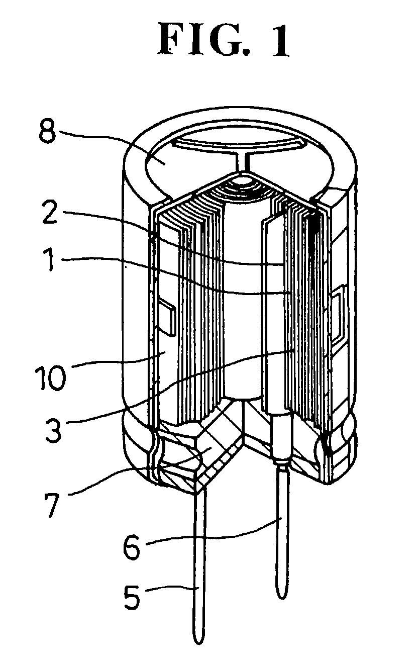
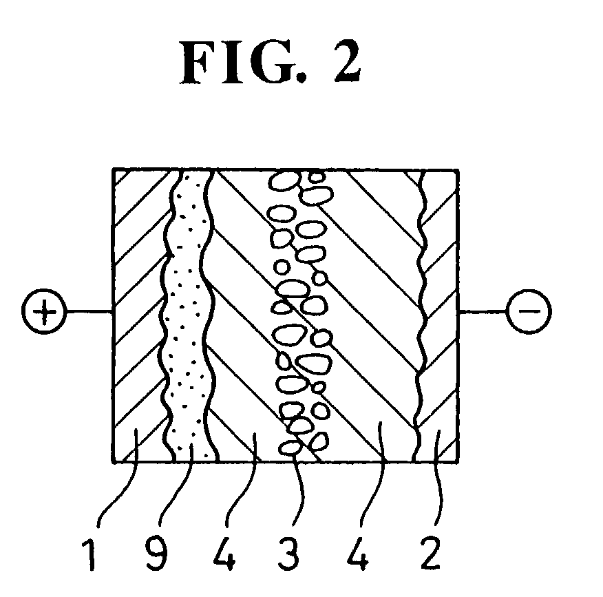
[0040] an insulating oxide film was formed on the surface of the anode foil by the anodic oxydization under the voltage 35 V Then, thus treated anode foil and the cathode foil of which surface was roughened by etching were rolled by holding the separator A between them, thereby obtaining a condenser element. Then, the condenser element was impregnated with 10 weight % ethylene glycol solution of anmonium salt of adipic acid. Thus, the electrostatic capacitance of the condenser element was 300 .mu.F at frequency 120 Hz. Then, the condenser element was impregnated with a solution of 1 part of ethylene dioxy thiophene which is a heterocyclic monomer and 4 parts of p-toluenesulphonic acidiron(II) which is an oxydizing agent and n-buthanol which is a polymerizing solution. By leaving the condenser element at 85.degree. C. for 60 minutes after completing the impregnation, a solid electrolyte of polyethylenedioxythiophene which is a chemically polymerized conductive po...

embodiment 2

[0041] [Embodiment 2]

[0042] In the embodiment 1, before forming the solid electrolyte of polyethylene dioxythiophene, the condenser element was impregnated in an aqueous solution of 1.0% polyethylenedioxythiophenepolystyrenesulphonic acid By drying the condenser element at 150.degree. C. for 5 minutes, a layer of polyethylenedioxythiophenepolystyrenesulphonate was formed. The solid electrolyte condenser was manufactured in the same manner as described in [Embodiment 1], except the above-mentioned processes.

embodiment 3

[0043] [Embodiment 3]

[0044] In the [Embodiment 1], in place of polyethylenedioxythiophene, the condenser element was impregnated with tetracyanoquinodimethane complex salt (TCNQ) The above-mentioned process was executed at a temperature higher than 200.degree. C. Then, by cooling the condenser element down to the room temperature, a solid electrolyte of TCNQ was formed in the condenser element. The solid electrolyte condenser was manufactured in the same manner as described in [Embodiment 1], except the above-mentioned processes.


PUM

PropertyMeasurementUnit
Linear densityaaaaaaaaaa
Percent by massaaaaaaaaaa
Diameteraaaaaaaaaa

Abstract

An object of the present invention is to provide a separator which is excellent in sticking and adhesion capability with the solid electrolyte, physically strong and highly heat-resistive and to provide a solid electrolyte condenser which is excellent in the impedance characteristic and leak current characteristic. In a solid electrolyte condenser comprising an anode foil, a cathode foil, a separator, the separator is made of a nonwoven fabric containing polyester resin or its derivative manufactured by the wet method. The condenser element is formed by rolling the anode foil and the cathode foil together with the separator between them. The solid electrolyte is provided between the anode foil and the cathode foil of the condenser element.

Description

[0001] 1. Technical Field of the Invention[0002] The present invention relates to a separator for a solid electrolyte condenser wherein a solid electrolyte lies between an anode foil and a cathode foil, and relates to a rolled type solid electrolyte condenser using the separator.[0003] 2. Description of the Prior Art[0004] As electronic devices are operated at higher frequency, the electrolyte condenser also is being desired to have a superior impedance characteristics at the higher frequency and a large capacitance. Recently, the rolled type solid electrolyte condenser using the solid electrolyte of high conductivity polymer has been studied in order to reduce the impedance at the higher frequency. On the other hand, the rolled type condenser wherein the anode foil and the cathode foil is rolled with the separator between has an advantage in increasing the capacitance, compared with laminated type condenser wherein the electrode foils are laminated, because the structure of the rol...

Claims


Application Information

Patent Timeline
IPC IPC(8): H01G9/02H01G9/028H01M50/414
CPCH01G9/02H01M2/162H01G11/52H01G11/56Y02E60/13Y02E60/10H01M50/44H01M50/414
Inventor MOROKUMA, MUNEHIRONITTA, YUKIHIROMIZOBUCHI, TAIJIJINZENJI, TERUYUKIYANASE, MASAAKI
Owner NIPPON KODOSHI
Why Eureka
Try Eureka