Such products are extremely sensitive to the presence of
electron-donating n-type materials, and very small concentrations of such n-type are sufficient to deactivate the p-type dopants and impair or destroy the performance and
operability of the integrated circuits, LEDs and blue lasers.
Similar detrimental effects are observed with similar low concentrations of water or hydrocarbons in the manufacturing
system.
A common requirement in these processes is that all reactants, catalysts, carriers, etc. must have the least practical contaminant level, since the products produced must be of very high purity.
However,
copper tends to migrate over a period of time, so it is necessary to construct barrier
layers in the
semiconductor to prevent the
copper migration.
Water is one of the most common and yet most difficult impurities to remove from the gases.
In the manufacture of such products,
moisture contents of the depositing gases which are in the ppm range are excessively wet.
While contaminant removal can be effected for short periods of time down to the 10 ppb level, the reactive effects of the hydride gases, especially ammonia, very quickly cause the materials to degrade and contaminate the gas
stream with
metal complexes.
Though pre-existing impurities may be reduced, the introduction of new impurities to the manufacturing process is unacceptable.
However, these have been relatively ineffective at reaching sufficiently low levels of decontamination.
Consequently, the problem of removal of contaminant levels down to .ltoreq.100 ppb from ammonia remains a significant problem in the field of production of high purity LEDs, blue lasers, semiconductors, and the like.
Those processes which are being used are expensive because of the very short service life of the decontaminating materials and the need for their frequent replacement.
In addition, since it is difficult to determine the exact rate of deterioration of the decontaminating materials in the presence of the ammonia, users of such decontaminating materials must schedule their discard and replacement at intervals less than the shortest expected service life.
To do otherwise would risk failure of a decontamination unit with the
resultant loss of contaminated product when the excessive contaminant concentrations reaches the production chamber through the failed unit.
Consequently, the current systems require that many if not most of the decontamination units must be discarded while they still have some degree of useful service life left, thus further increasing the expense of the
system operations.
Therefore the more that a process deviates from these anticipated parameters, the less acceptable it is.
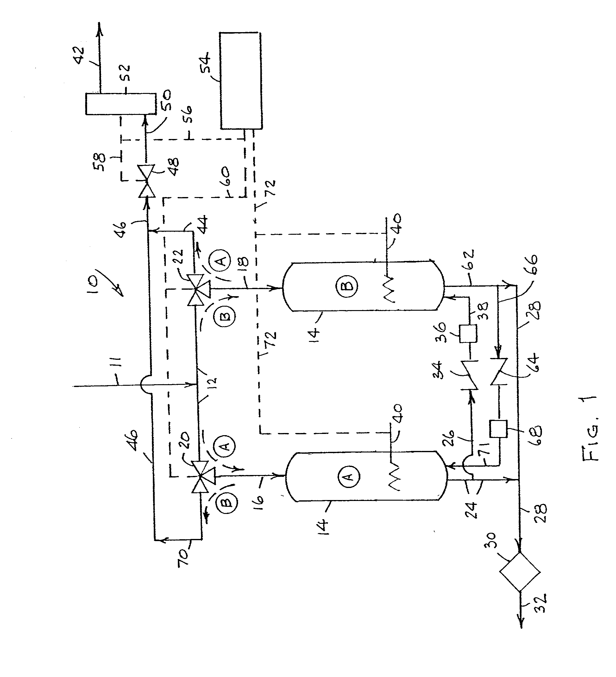
While ammonia decontamination systems have been described that include multiple adsorbent beds or vessels that alternate in decontaminating and regenerative function, such systems suffer drawbacks in that they either a) require the periodic replacement of adsorbent, e.g., a
getter alloy, and / or b) involve a
regenerative process that relies on the administration of gas from outside the system to generate fresh adsorbent, e.g.,
alumina, from contaminant-saturated adsorbent.

