Electrode of a vacuum valve, a producing method thereof, a vacuum valve, a vacuum circuit-breaker and a contact point of the electrode
a vacuum valve and electrode technology, applied in the direction of contact manufacturing, air-break switch, contact, etc., can solve the problems of low productivity, high production cost, and oil staying in the pores of the pores, and adversely affecting the vacuum valve breaker performan
- Summary
- Abstract
- Description
- Claims
- Application Information
AI Technical Summary
Benefits of technology
Problems solved by technology
Method used
Image
Examples
first embodiment
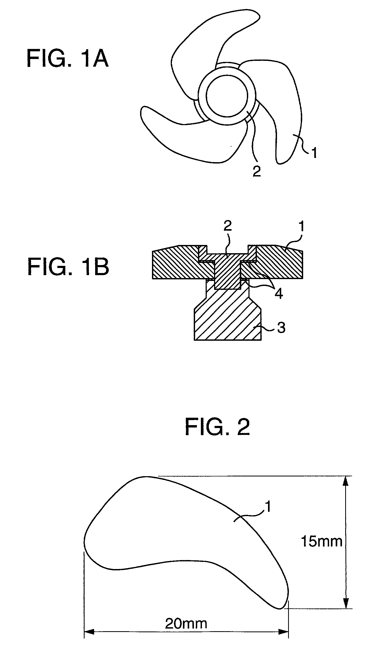
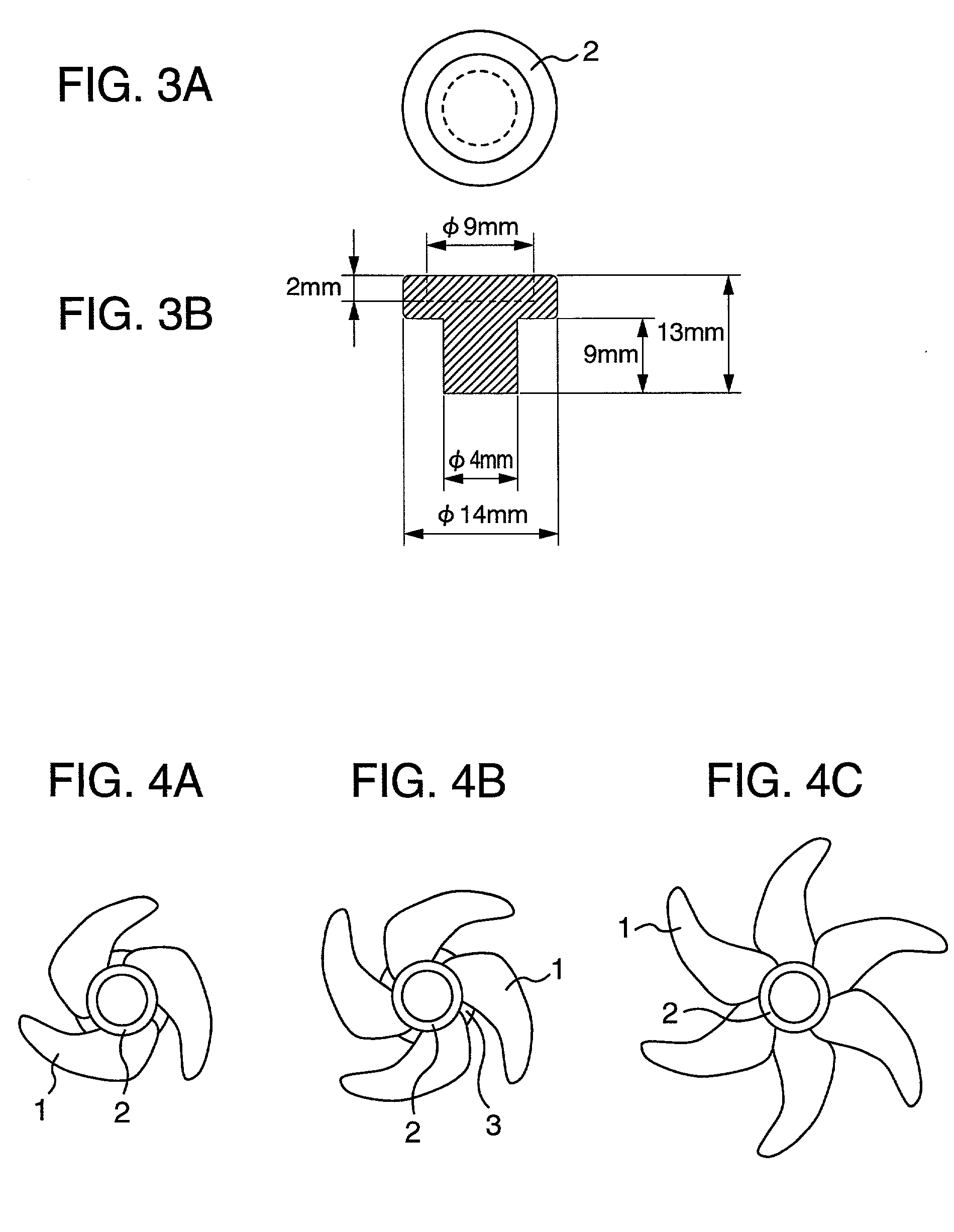
[0052] FIG. 1A is a plan view of an electrode according to the invention. valve FIG. 1B is a cross sectional view of the electrode shown in FIG. 1A. The electrode comprises vane type contact point members 1, a circular contact point member 2, an electrode rod 3, and a solder 4.
[0053] The vane type contact point members 1 were manufactured as follows. A copper powder of the high-conductivity metal and a chromium powder of the heat-resistant metal were mixed with each other in a composition of 65:35 (Cu:Cr) by weight, which mixture was filled in a die having a cavity configuration by which a form of the vane type contact point member 1 can be obtained, the contact point member 1 as a sintered product having the size indicated in FIG. 2. The copper powder had a particle size of not more than 60 .mu.m. The chromium powder had a particle size of not more than 104 .mu.m. The amount of the metal powder mixture to be filled in the die was determined so that the sintered product has a desire...
example 2
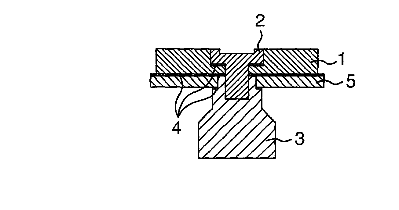
[0061] FIGS. 5A and 5B show an electrode produced by the same way as the first embodiment, which is provided with a reinforcement plate 5 on the back of the vane type contact point members 1.
[0062] This electrode is manufactured as follows. The electrode rod 3 is made of an oxygen-free copper like as in the first embodiment. The reinforcement plate 5 made of stainless steel of JIS SUS 304 is machined to a circular plate having a center opening. The vane type contact point members 1 are also machined so that the circular contact point member 2 can be engaged therewith. The vane type contact point members 1, the circular contact point member 2, and the electrode rod 3 are superimposed with solders 4 therebetween as shown in FIG. 5B. The solder 4 was of a Cu-Mn alloy. The assembly is then heated at 980.degree. C. for eight minutes under vacuum of not higher than 8.2.times.10.sup.-4 Pa to obtain the electrode as shown in FIGS. 5A and 5B. The outer diameter of the reinforcement plate 5 i...
example 3
[0065] FIG. 6 shows a conventional contact point 6 as a comparative example which is an integral vane type being provided with vane figures by forming slit-grooves 6a.
[0066] This conventional contact point member is produced as follows. A mixture of a copper powder as a high-conductivity metal and a chromium powder as a heat-resistant metal in a composition rate of, by weight, Cu:Cr=75:25, is filled in a forming and compacting die to produce an integral vane type contact point member 6, which has dimensions as shown in FIG. 2, by sintering. The powder mixture has the same particle size as that of producing the vane type contact point member 1. The powder mixture filled in the die was compacted by a hydraulic press under a pressure of 120 MPa. The thus obtained compact had a relative density of 61%. The compact was sintered under the same conditions as those of sintering to produce the vane type contact point members 1 so that the integral contact point member 6, as shown in FIG. 6, ...
PUM
| Property | Measurement | Unit |
|---|---|---|
| pressure | aaaaa | aaaaa |
| particle sizes | aaaaa | aaaaa |
| pressure | aaaaa | aaaaa |
Abstract
Description
Claims
Application Information
 - R&D
- Intellectual Property
- Life Sciences
- Materials
- Tech Scout
- Unparalleled Data Quality
- Higher Quality Content
- 60% Fewer Hallucinations
Browse by: Latest US Patents, China's latest patents, Technical Efficacy Thesaurus, Application Domain, Technology Topic, Popular Technical Reports.
© 2025 PatSnap. All rights reserved.Legal|Privacy policy|Modern Slavery Act Transparency Statement|Sitemap|About US| Contact US: help@patsnap.com


