Luminescent element material and luminescent element comprising the same

a technology of luminescent elements and material, which is applied in the direction of discharge tube/lamp details, group 5/15 element organic compounds, diaryl/triaryl methane dyes, etc., can solve the problems of thin film clouding, poor durability, and shorten the life of the devi

Inactive Publication Date: 2003-09-11
TORAY IND INC
View PDF11 Cites 139 Cited by
  • Summary
  • Abstract
  • Description
  • Claims
  • Application Information

AI Technical Summary

Problems solved by technology

However, many conventional emissive materials, hole transporting materials and electron transporting materials lack durability, and crystallization takes place due to the heat evolved from the device by the prolonged passage of current, so that the device life is shortened.
In particular, taking the case of the electron transporting material, with many of the existing materials there are problems such as the desired emission colour not be obtained for reasons such as interaction with the emissive material or there being admixed light emission by the electron transporting material itself, while even where highly efficient emission is obtained the durability is poor.
In U.S. Pat. No. 5,393,614, a specific phenanthroline derivative is used as the electron transporting material, but while highly efficient emission is shown there is crystallization during prolonged operation, and the thin film turns cloudy.
Quinolinol metal complexes and benzoquinolinol metal

Method used


Image

  • Luminescent element material and luminescent element comprising the same
  • Luminescent element material and luminescent element comprising the same
  • Luminescent element material and luminescent element comprising the same

Examples


example 2

Synthesis of Connecting Unit 2

[0100] 11.9 g of 2-bromobiphenyl was converted to the Grignard form in THF using 1.7 g of metal magnesium, then this reacted with 13.4 g of 2,4-diethyl-9-thioxanthone at from room temperature to 50.degree. C. and, by treatment in the normal way, 2,4-diethyl-9-(2-biphenyl)-9-thioxantheno-l was obtained. This was heated in acetic acid to which a small amount of hydrochloric acid had been added, so that water was eliminated and, by treatment in the usual way, Connecting Unit 2 (13.8 g) shown below was obtained. .sup.1H-NMR (CDCl.sub.3, ppm): 7.8 (m, 2H), 7.6 (d, 2H), 7.4 (m, 3H), 7.2 (m, 2H), 7.1 (t, 1H), 6.9 (s, 1H), 6.8 (t, 1H), 6.5 (d, 1H), 6.2 (s, 1H), 2.9 (m, 2H), 2.3 (m, 2H) 1.4 (t, 3H), 0.9 (t, 3H) 35

example 3

Introduction of Acetyl Groups into Connecting Unit 1: Connecting Unit 1'

[0101] Connecting Unit 1 (8.5 g) was reacted with 4.5 g of acetyl chloride and 7.5 g of aluminium chloride at 50.degree. C. in 1,2-dichloroethane and, by treatment in the normal way, Connecting Unit 1' (13.1 g) shown below was obtained. .sup.1H-NMR (CDCl.sub.3, ppm): 8.0 (d, 1H), 7.9 (d, 2H), 7.8 (d, 1H), 7.7 (s, 1H), 7.4 (t, 1H), 7.3-7.1 (m, 5H), 7.0 (s, 1H), 6.8 (t, 1H) 6.3 (d, 1H), 2.5 (s, 3H), 2.3 (s, 3H) 36

example 4

Synthesis of the Benzoquinoline Derivative (BQ-1))

[0102] 23.8 g of 2-bromobiphenyl was converted to the Grignard form in THF using 3.4 g of metal magnesium, then this reacted with 18.0 g of 9-fluorenone at from room temperature to 50.degree. C. and, by treatment in the normal way, 9-(2-biphenyl)-9-fluorenol was obtained. This was heated in acetic acid to which a small amount of hydrochloric acid had been added, so that water was eliminated and, by treatment in the usual way, Connecting Unit 1 (18.5 g) was obtained. Next, Connecting Unit 1 (15.8 g) was reacted with 8.6 g of acetyl chloride and 14.7 g of aluminium chloride at 50.degree. C. in 1,2-dichloroethane and, by treatment in the normal way, 2,2'-diacetyl-9,9'- spirobifluorene (11.2 g) was obtained. This diacetyl compound (2.3 g) was reacted with 2.0 g of 1-amino-2-naphthalenecarbaldehyde and 1.6 g of potassium hydroxide at 60.degree. C. in dioxane and, by treatment in the normal way, there was obtained BQ-1 (1.5 g) shown below....


PUM

PropertyMeasurementUnit
Angleaaaaaaaaaa
Currentaaaaaaaaaa
Currentaaaaaaaaaa

Abstract

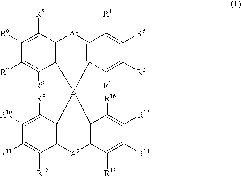
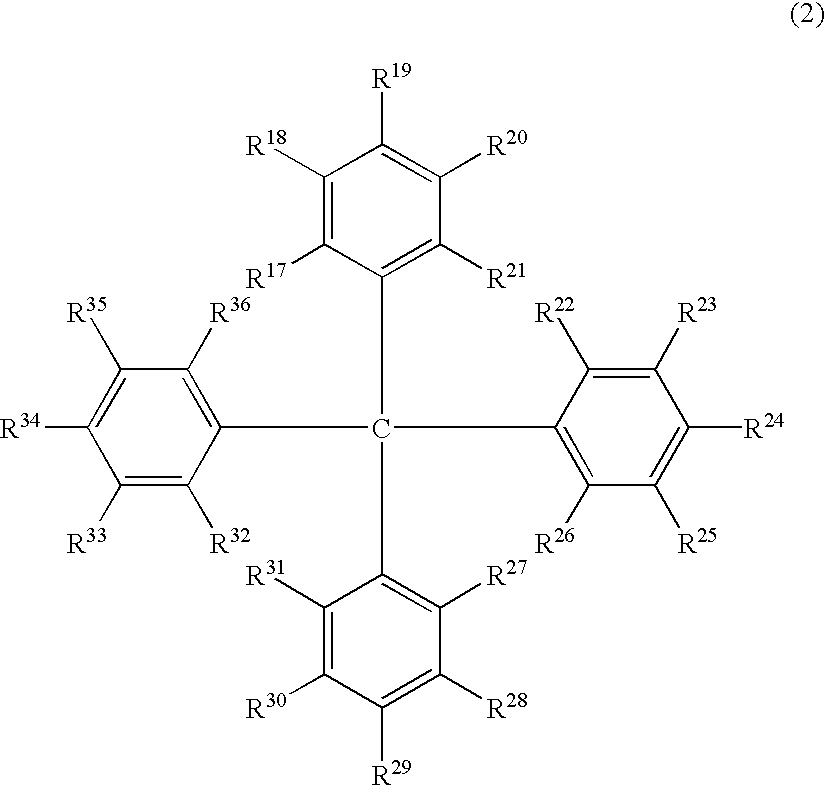
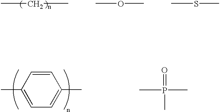
The light emitting device of the present invention relates to a light emitting device which is characterized in that it is a device with an emissive substance present between an anode and cathode, and which emits light by means of electrical energy, and said device has a least one type of compound denoted by (a) to (d) below. (a) A compound having a plurality of 1,7-phenanthroline skeletal structures (b) A benzoquinoline derivative (c) A spiro compound represented by general formula (1) A1 and A2 are each selected from single bonds, substituted or unsubstituted alkyl chains, ether chains, thioether chains, ketone chains and substituted or unsubstituted amino chains. However, A1<> A2. Z represents carbon or silicon. R1 to R16 are each selected from hydrogen, alkyl group, cycloalkyl group, aralkyl group, alkenyl group, cycloalkenyl group, alkynyl group, hydroxyl group, mercapto group, alkoxy group, alkylthio group, aryl ether group, aryl thioether group, aryl group, heterocyclic group, halogen, haloalkane, haloalkene, haloalkyne, cyano group, aldehyde group, carbonyl group, carboxyl group, ester group, carbamoyl group, amino group, nitro group, silyl group, siloxanyl group and a cyclic structure formed with an adjacent substituent. (d) A tetraphenylmethane derivative represented by general formula (2) R17 to R36 are each selected from hydrogen, alkyl group, cycloalkyl group, aralkyl group, alkenyl group, cycloalkenyl group, alkynyl group, hydroxyl group, mercapto group, alkoxy group, alkylthio group, aryl ether group, aryl thioether group, aryl group, heterocyclic group, halogen, haloalkane, haloalkene, haloalkyne, cyano group, aldehyde group, carbonyl group, carboxyl group, ester group, carbamoyl group, amino group, nitro group, silyl group, siloxanyl group and a cyclic structure formed with an adjacent substituent. However, at least one of R17 to R36 is selected from substituents represented by general formula (3). -X-Ar (3) X is a single bond or is selected from the following, and Ar denotes a condensed aromatic ring or heteroaromatic ring. In the case where X is phosphorus oxide, then Ar represents an aromatic hydrocarbon or heteroaromatic ring. n is an natural number.

Description

[0001] The present invention relates to light emitting device materials and to a light emitting device which can convert electrical energy into light and can be used for display elements, flat panel displays, back lights, lighting, interiors, signs, signboards, electronic cameras, light signal generators and the like.TECHNICAL BACKGROUND[0002] There has recently been considerable research into organic multi-layered thin film light-emitting devices which emit light when electrons injected from a cathode and holes injected from an anode recombine within an organic fluorescent body interposed between the electrodes. Such devices are a focus of attention on account of their characteristics of thin shape, high luminance at low driving voltage and polychromic light emission based on suitable selection of the fluorescent materials.[0003] Numerous research organizations have been carrying out such research since C. W. Tang and co-workers at Kodak first described the fact that an organic mul...

Claims


Application Information

Patent Timeline
IPC IPC(8): C07C15/28C07C15/52C07D209/14C07D209/86C07D213/53C07D215/12C07D219/02C07D221/10C07D235/20C07D241/42C07D249/08C07D263/32C07D263/62C07D263/64C07D271/10C07D271/107C07D277/66C07D311/96C07D405/14C07D407/14C07D409/14C07D413/14C07D417/14C07D519/00C07F7/08C07F9/38C07F9/6561C09K11/06H01L51/00H01L51/30H01L51/50
CPCC07C15/28Y10S428/917C07D209/14C07D209/86C07D213/53C07D215/12C07D219/02C07D221/10C07D235/20C07D241/42C07D249/08C07D263/32C07D263/64C07D271/107C07D277/66C07D311/96C07D405/14C07D407/14C07D409/14C07D413/14C07D417/14C07F7/0807C07F7/0814C07F9/3813C07F9/6561C09K11/06C09K2211/1003C09K2211/1007C09K2211/1011C09K2211/1029C09K2211/1033C09K2211/1037C09K2211/1044C09K2211/1048C09K2211/1059C09K2211/1088C09K2211/1092C09K2211/1096H01L51/0036H01L51/005H01L51/0058H01L51/0059H01L51/0067H01L51/007H01L51/0072H01L51/008H01L51/0081H01L51/0094H01L51/50H01L51/5012C09B11/04C09B11/12C09B11/28C09B23/0008C09B23/04C09B23/148C09B57/00C09B57/007C09B57/10C07C15/52H10K85/60H10K85/113H10K85/6565H10K85/626H10K85/631H10K85/322H10K85/324H10K85/654H10K85/6572H10K85/40H10K50/11H10K50/00H05B33/14C09K2211/1022
Inventor TOMINAGA, TSUYOSHIKITAZAWA, DAISUKEMAKIYAMA, AKIKOHAMA, AKIRA
Owner TORAY IND INC
Why Eureka
Try Eureka