

Method of making amorphous and ceramics via melt spinning
a technology of amorphous and ceramics and amorphous materials, which is applied in the direction of glass forming apparatus, glass making apparatus, glass shaping apparatus, etc., can solve the problems of not being formed into bulky or complex shapes, and achieve the effects of reducing the melting temperature of the overall system, improving processing, and reducing the melting eutecti
- Summary
- Abstract
- Description
- Claims
- Application Information
AI Technical Summary
Benefits of technology
Problems solved by technology
Method used
Image

Examples
examples 1-2
[0130] A 250-ml polyethylene bottle (7.3-cm diameter) was charged with a 50-gram mixture of various powders (as shown below in Table 1, with sources of the raw materials listed in Table 2), 75 grams of isopropyl alcohol, and 200 grams of alumina milling media (cylindrical shape, both height and diameter of 0.635 cm; 99.9% alumina; obtained from Coors, Golden, Colo.). The contents of the polyethylene bottle were milled for 16 hours at 60 revolutions per minute (rpm), the milling media were removed and the slurry was poured onto a warm (approximately 75.degree. C.) glass ("PYREX") pan where it dried within 3 minutes. The dried powder was then screened through a 70-mesh screen (212-micrometer opening size screen) with the aid of a paintbrush.
1TABLE 1 Example Weight percent of components Batch amounts, g 1 Al.sub.2O.sub.3: 38.5 Al.sub.2O.sub.3: 19.3 La.sub.2O.sub.3: 42.5 La.sub.2O.sub.3: 21.3 ZrO.sub.2: 19.0 ZrO.sub.2: 9.5 2 Al.sub.2O.sub.3: 57.5 Al.sub.2O.sub.3: 28.8 Y.sub.2O.sub.3: 27...
example 3
[0132] Approximately 7 grams of the feed particles of Example 1 were cold isostatically pressed (CIPed), at 207 megapascals (MPa) (30 ksi) in a rubber bag, into a pellet, 1 centimeter (cm) in diameter, and 5 cm in length. Cold isostatic pressing was done in oil (to apply pressure uniformly from all directions) so, to protect the sample from soaking in oil, the sample was placed in a rubber bag (diameter of 1 cm) to contain the samples during CIPing.
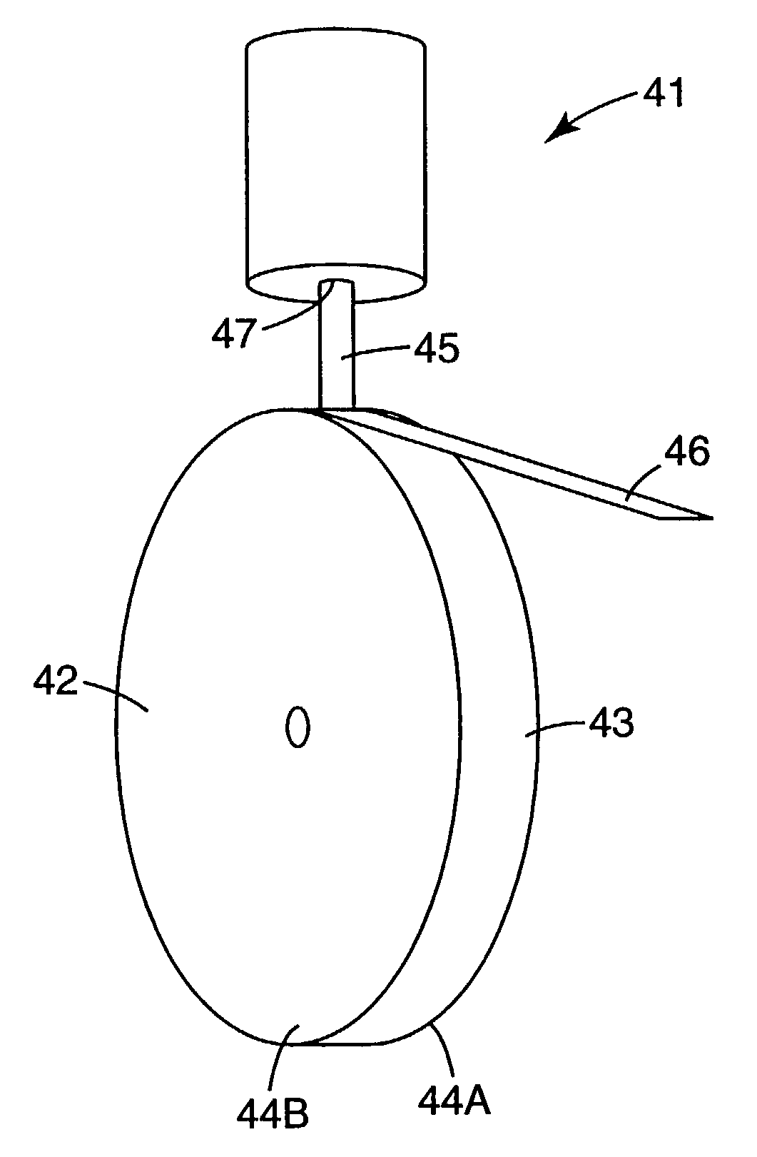
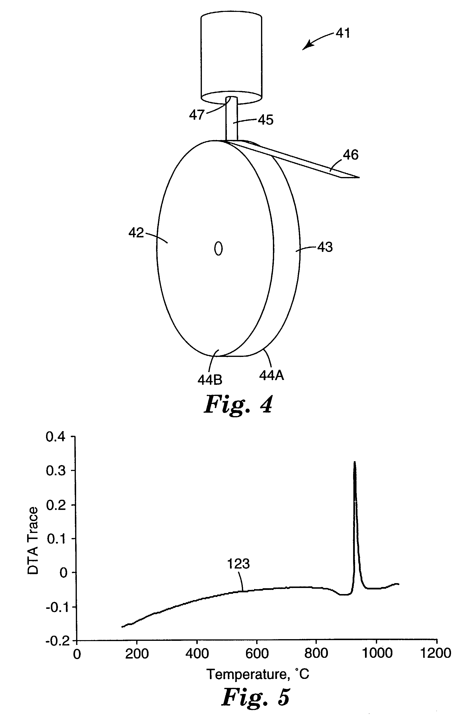
[0133] The pellet was placed in a graphite cylindrical crucible with a diameter of 1.25 cm. The bottom of the crucible was tapered and approximately 2 millimeters (mm) thick at the orifice opening. The orifice opening was 0.82 mm in diameter. The sample was heated using a standard 15 kilowatt (KW) (operating at 450 kHz) inductively heated unit under a partial pressure of He gas. No attempt was made to monitor or control the temperature of the chamber. Heating and melting occurred very rapidly, within a few seconds. After initial melting w...
example 4
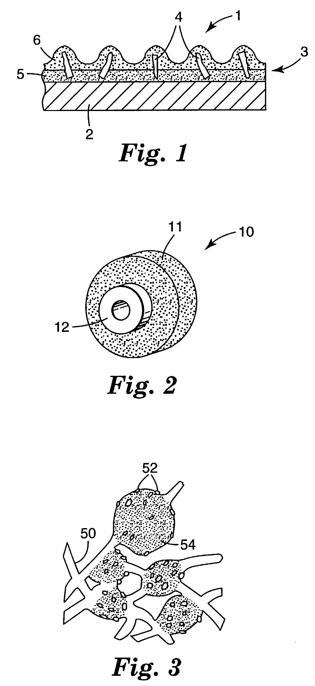
[0134] A second charge of 7 grams of the feed particles of Example 1 was prepared and melt-spun as described in Example 3, except the orifice opening was 1.1 mm in diameter. Again a non-continuous melt stream was established. A fraction of the melt hit the rotating copper wheel and was expelled as spherical particles. However, the majority of the melt was deformed and quenched by the copper wheel resulting in whiskers and flakes. Visual inspection using optical microscopy showed the whiskers and flakes were transparent, which suggest amorphous material.
PUM
| Property | Measurement | Unit |
|---|---|---|
| Length | aaaaa | aaaaa |
| Percent by mass | aaaaa | aaaaa |
| Percent by mass | aaaaa | aaaaa |
Abstract
Description
Claims
Application Information