Through weld for aluminum or aluminum alloy base metals by using high-density energy beams

a technology of high-density energy beams and base metals, which is applied in the direction of laser beam welding apparatus, welding/soldering/cutting articles, manufacturing tools, etc., can solve the problems of limited application range of this method, the tendency of laser beams to reflect, and the inability to continue continuous welding at the site, etc., to increase the viscosity of melted metal, and reduce the quantity of filler needed

Inactive Publication Date: 2004-05-06
HONDA MOTOR CO LTD
View PDF6 Cites 22 Cited by
  • Summary
  • Abstract
  • Description
  • Claims
  • Application Information

AI Technical Summary

Benefits of technology

0038] Therefore, the shield gas S blown from the torch 8 forms a shield gas ambience G2 that covers the surface of the welding site la of the upper welding base metal 1 and intercepts the surface of the welding site 1a from the open air. The shield gas S blown from the nozzle 9 also covers the surface of the site 2a of the submerged-scar B, forms the shield gas ambience (inert gas ambience) G3 and intercepts the surface of site 2a of the submerged-scar B from the open air. Since the shield gas ambiences G2 and G3 respectively intercept the welding site la and the site 2a of the submerged-scar B from both oxygen and hydrogen in the air, the forming of the blow holes and the surface oxidation of the beads due to the enrollment as reaction with the hydrogen and oxygen included in the open air can be prevented.
0039] By setting the movement speed of the above manipulator to which the nozzle 9 is installed to coincide with the movement speed of the torch 8 and to synchronize the torch 8 and the nozzle 9 in the movement from the starting point to the ending point and blowing the shield gases S from the nozzle 9 and the torch 8 at the same time as the irradiation of laser L, the keyhole is pushed up from the side of the submerged-scar B and the beads are quickly cooled by the shield gas S, the viscosity of the melted metal quickly increases and therefore the generation of projection T and the under-fill is suppressed. Accordingly, the submerged-scar B is formed in such a shape that the height of the extrusion is substantially constant along the weld line, the outer curve of the cross section of the extrusion against the downward is smooth and a sound welded joint that has strong bonding strength is obtained. It is also possible to reduce the quantity of the filler necessary to refill because the under-fill is suppressed in this welding process. In short, this second embodiment can solve the conventional technical problem as well as the first embodiment can.

Problems solved by technology

It may be possible to suppress the generation of submerged-scar by decreasing the thermal heat input in the conventional through weld of aluminum base metal by using a laser beam a. However, in this method, the problem that the laser beam tends to be reflected and the continuous welding may cease in sites may happen.
However it is necessary to select thick welded base metals for this method, therefore it is a problem that the range of application of this method is limited
For this case, it is necessary to rework for the post process as stripping off the projections and surface polishing of the welding sites and there is a problem of additional time-consuming works.

Method used


Image

  • Through weld for aluminum or aluminum alloy base metals by using high-density energy beams
  • Through weld for aluminum or aluminum alloy base metals by using high-density energy beams
  • Through weld for aluminum or aluminum alloy base metals by using high-density energy beams

Examples


example 1

[0041] FIG. 3 shows the plan views (upper schematics in the fields of columns) and the side views (lower schematics in the fields of columns) of the welded joints regarding to the through weld described in the first embodiment for the cases such that the back-shield gas is supplied, in other words, the shield gas S is blown to the site 2a of the submerged-scar B and the ambience of the shield gas is made and no back-shield gas is supplied, in other words, no shield gas is blown thereto.

[0042] Changing the pairs of the thickness of welding base metals 1 and 2 and the welding speed under the same flow ratio of the shield gas S supplied to the side of the submerged-scar B and that supplied to the laser irradiation side kept constant, the heat input against the welding site la of the upper and the lower welding base metals 1 and 2 per unit time by the laser beam L is reversely proportional to the welding speed. The silver frost like projection T is formed on the surface of the submerged...

example 2

[0043] FIG. 4 shows a cross sectional view of the welded joint regarding to the through weld described in the first embodiment for a case that the gas flow rate of the shield gas supplied onto the laser irradiation side is kept constant and the shield gas S supplied onto the submerged-scar side is varied as 10 1 / min., 25 1 / min. and 40 1 / min. FIG. 5 shows the plan views (upper schematics in the fields of columns) and the side views (lower schematics in the fields of columns) of the welded joint in the same conditions. In order to study the effect of the shield gases for the welded joints against the kind of gases, three inert gases as Ar (argon gas) , N2 (nitrogen gas) and He (helium gas) have been used. For this case, the shield gases have been blown to the submerged-scar B in the upper direction beneath the submerged-scar B. For the purpose of comparison to a nominal condition, a through weld by using compressed air has been carried out.

[0044] As shown in FIG. 4, changing the flow ...

example 3

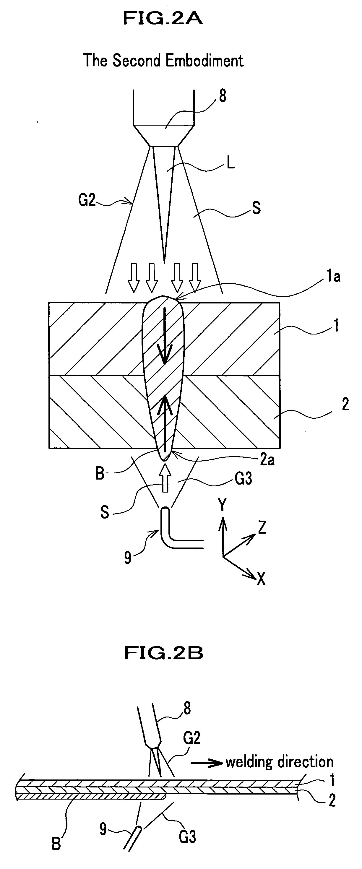
[0046] FIG. 6 shows a cross sectional view of the welded joint regarding to the through weld described in the second embodiment for the case when the blowing direction of the shield gas S is changed in accordance with the direction of the nozzle against the submerged-scar B.

[0047] As shown in FIG. 6, the projection T is formed on the submerged-scar when no back-shield gas is supplied however the shape of the formation of the projection T changes in accordance with the blowing direction of the shield gas supply against the submerged-scar B.

[0048] In more details to explain, setting the nozzle 9 obliquely upward direction toward the starting point from the ending point on the weld line or toward the ending point from the starting point, then the projections have been sometimes formed on the submerged-scar for the obliquely upward blowing of the shield gas. However, the forming of the projections has been prevented to be formed when the shield gas has been vertically blown beneath the ...


PUM

PropertyMeasurementUnit
speedaaaaaaaaaa
energyaaaaaaaaaa
densityaaaaaaaaaa

Abstract

This invention provides a new through weld method to carry out welding of a base metal made of aluminum or that of aluminum alloy using high energy beams wherein a shield gas ambience (an inert gas ambience) to cover a welding site in a submerged-scar is formed, even a shield gas ambience (an inert gas ambience) to cover a welding site irradiated by the high energy beams. Since the former shield gas ambience to cover the submerged-scar pushes the keyhole against the gravity and/or the gas pressure force of the latter shield gas supplied to the laser irradiation side, then the forming of hang down of beads and the resultant projection of the welding base metal are prevented.

Description

[0001] This invention relates to a through weld method applied to a base metal made of aluminum or that of aluminum alloys by using high-density energy beams, especially to the weld method that prevents a hang down of beads made of the melted base metal in welding operation.[0002] The through weld by using high-density energy beams, such as a laser beam, an electron beam et al., generates little thermal deformation and less segregation of the fused metal due to quick cooling for solidification at the welding sites, therefore it has been used for the stack welding and butt welding of steel materials especially thin steel sheets.[0003] FIG. 8A shows a cross sectional view of the conventional welded joint of aluminum and aluminum alloy base metals. FIG. 8B shows a cross sectional view of the welding site of the conventional through weld of rolling steel plate (called as "SP", hereinafter). FIG. 8C shows a cross section view of the through weld of an aluminum base metal by using MIG (Me...

Claims


Application Information

Patent Timeline
Patent Type & Authority Applications(United States)
IPC IPC(8): B23K26/21B23K15/00B23K26/14B23K26/24B23K26/32B23K103/10
CPCB23K15/0066B23K26/123B23K26/1452B23K2203/10B23K26/246B23K26/3226B23K26/1458B23K26/32B23K26/1438B23K26/1462B23K26/244B23K2103/10
Inventor YAHABA, TAKANORITAKIKAWA, MASATOSONODA, HIROBUMIIBUKURO, JUNICHIOKUYAMA, KENJIUKENA, TOSHIYASUICHIYAMA, YASUTOMO
Owner HONDA MOTOR CO LTD
Why Eureka
Try Eureka