

Process and apparatus for plasma activated depositions in a vacuum
a plasma activated deposition and vacuum technology, applied in the field of vacuum activated deposition process and apparatus, can solve the problems of low deposition efficiency, poor evaporation efficiency, and inability to achieve the effect of reducing the cost of capital equipment, neither operator or capital equipmen
Inactive Publication Date: 2004-06-24
UNIV OF VIRGINIA +1
View PDF11 Cites 70 Cited by
- Summary
- Abstract
- Description
- Claims
- Application Information
AI Technical Summary
Benefits of technology
[0037] A further object of the present invention is to provide a process and apparatus which allows the plasma activation of the condensing vapor to provide, both for nonreactive as well as reactive deposition, carefully selected density structures on conductive as well as on nonconductive substrate surfaces. The effectiveness of the process and the apparatus should be guaranteed in a pressure range from about 10.sup.-4 mbar up to about atmospheric pressure.
[0038] Still yet, a further object of the present invention is to provide a process and apparatus which allows the plasma activation of vapor, which is entrained in a gas stream, to provide for conveying the ionized particles by stream despite the strong steadily charge carrier loss.
[0039] Moreover, a further object of the present invention is to provide a process for plasma activating electron beam directed vapor deposition using a hollow cathode arc discharge which makes efficient use of the electrons of the directed low voltage electron beam that it generates to ionize gas and vapor atoms in a focused flow.
[0041] In addition, an object of the present invention is to provide a process for plasma activating electron beam directed vapor deposition which uses a hollow cathode arc discharge for the extreme energy modulation of vapor and gas atoms ionized by the discharge's directed low voltage electron beam in a sequence of predetermined steps, using different evaporants and reactive gases in each step, including steps without plasma activation, so that well defined layer stacks with very distinct single layer properties can be created.
[0042] Finally, a further object of the present invention is to provide an apparatus for plasma activating electron beam directed vapor deposition which uses a hollow cathode arc discharge and which is continuous, automated, reliable and neither operator or capital equipment intensive.
Problems solved by technology
This diffuse distribution leads to coating nonuniformity for large area arrays and extremely low deposition efficiencies when coating, for example, small or curved surfaces such as 100 .mu.m diameter continuous fibers with metal (to make composites) or 3 cm long aircraft engine turbine blades with ceramic (to make thermal barrier coatings).
When a gas is introduced into the process chamber for reactive evaporation, the focus of the evaporant may become even worse (cos.sup.1 .theta.) as the result of collisions between the vapor stream atoms and background gas atoms in the chamber.
While the above described technologies combine deposition speed and efficiency, extensive study has demonstrated that they lack some key ingredient that allows them to form high quality layers possessing a wide range of easily selected microstructures--from porous, columnar to fully dense polycrystalline.
They have a limited ability to combine efficient, high rate deposition with precisely selected deposition energies.
Instead, because of their underlying inherent performance characteristics, their practical use is restricted to operation in a pressure range between 10.sup.-4 mbar and 0.1 mbar.
Not only do these standard plasma techniques have difficulty operating in the higher pressure regime of directed vapor deposition but also they have a limited ability to ionize gas and vapor atoms in a system at any pressure.
However, once the atomic density increases (e.g. in the high rate, elevated pressure regime of electron beam directed vapor deposition), the plasma density that can be created with these discharges is too small to achieve any effective improvement of the density in the deposited layers (See S. Schiller, H. Morgner, N. Schiller and S. Straach, High Rate Coating of plastic Films and Plastic Sheets with Clear Oxide Layers, Paper presented on 1997 Joint International Meeting ECS / ISE in Paris, August 31-Sep. 5, 1997, paper published in Metallized Plastics 5&6: Fundemental and Applied Aspects, p.
Although techniques like glow-discharge plasma, thermionic cathode plasma, radio-frequency plasma and microwave plasma, with magnetic amplification, are unable to create high plasma densities, it is known that a very high plasma density can be achieved by low voltage arc discharges (e.g. hollow cathode arc discharges).
However, this method cannot be transferred to gas stream guided vapor deposition.
However, to penetrate the high particle density of a gas and vapor directed vapor deposition system, it is necessary to apply very high acceleration potential to the electrons (e.g. 60-70 kV for electron acceleration in Wadley et al. system), and therefore precludes use of this type of low voltage arc configuration in directed vapor deposition systems.
This Halpern method is not suited for high rate deposition by two reasons.
Firstly, the energy available for evaporation is mainly supplied by the anode fall of the plasma discharge.
This energy is insufficient for high rate evaporation.
Still, these arrangements are not well suited for plasma activation of a concentrated vapor beam with very high particle density flowing with high velocity.
The spread plasma does not match effectively with the localized gas and vapor stream.
Such magnetic fields can not be strongly localized resulting in an unacceptable interference of the high-energy e-beam impacting its ability to function properly for evaporation negatively.
Still, this DE'012 configuration has several substantial drawbacks.
First, the pathway for the electrons of the directed low voltage electron beam, from the orifice of the hollow cathode tube to the vapor beam, is too long.
This results in a drastic energy loss for the low voltage beam electrons in the isotropic residual gas surrounding the vapor beam.
Due to the small distances in DVD configuration the magnetic fields from the plasma guidance and the strong circular magnetic field surrounding the power supply cables and the plasma discharge resulting from the high discharge current of the hollow cathode arc discharge, typically in the range of about one hundred amperes, leads to relatively high magnetic field strengths could negatively impact the ability of the high energy e-beam to function properly for evaporation.
This means that shielding is not possible in the vicinity of the vapor source crucible.
This restrictions makes it difficult to ensure that the e-beam pathway close to the crucible is not influenced by the magnetic field of the plasma discharge in the system configuration described in DE'012.
Nonsystematic deviations from constant plasma conditions can often occur in hollow cathode arc discharges, leading to sudden, undesirable shifts in the position of the evaporation spot in the crucible.
Such position shift of the evaporation spot makes the evaporation unstable, especially from crucibles with small diameter.
However, high voltage electrons are not well suited to the creation of high ionization percentages due to the dramatic decreasing of the ionization cross section with high electron energy.
Method used
View moreImage
Smart ImageViewing Examples

Examples
example no.1
EXAMPLE NO. 1
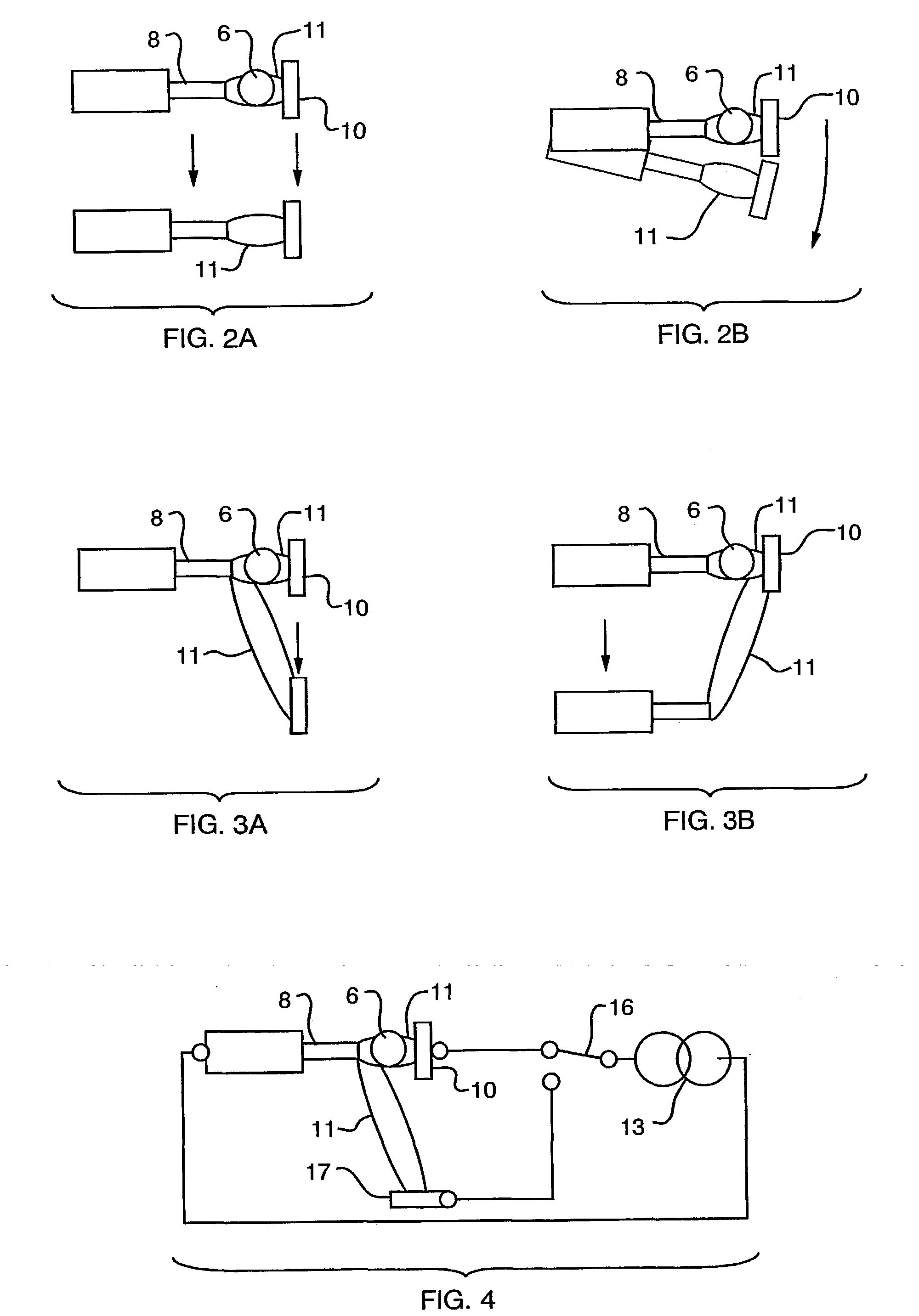
[0082] FIGS. 6-7 are schematic drawings representing an exemplary embodiment of the present invention, wherein FIG. 6 illustrates an enlarged partial view of the embodiment of FIG. 6.
Login to View More PUM
| Property | Measurement | Unit |
|---|---|---|
| distance | aaaaa | aaaaa |
| bias voltage | aaaaa | aaaaa |
| vapor atom energy | aaaaa | aaaaa |
Abstract
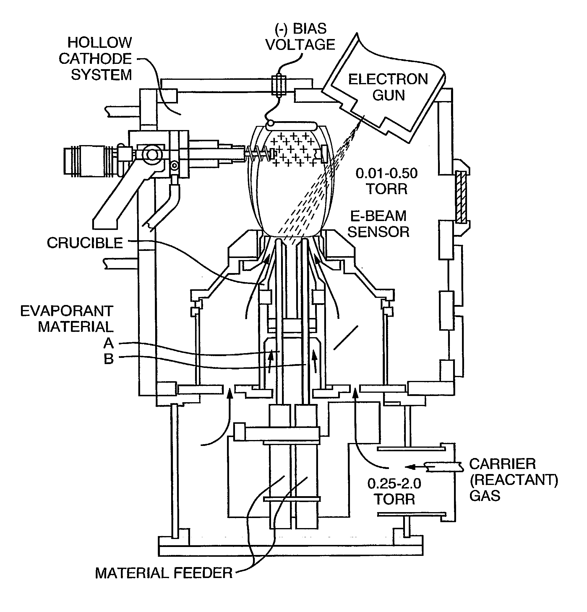
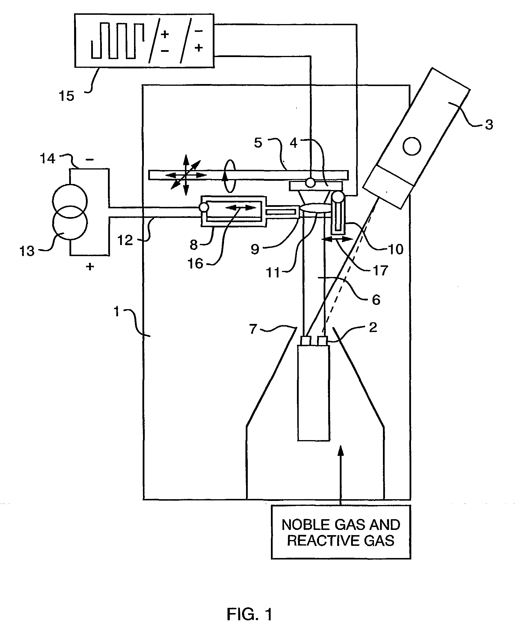
Plasma deposition apparatus (1) and method that allows metal or nonmetal vapor (6) to be generated by electron-beam evaporation, guides that vapor using a noble gas stream (containing reactive gases in cases of reactive evaporation), ionizes the dense directed gas and vapor stream at working pressures above about 0.0001 mbar using a hollow cathode plasma arc discharge (11), and conveys the ionized vapor and / or gas stream towards the substrate (4) for impact on the surface at energies varying from thermal levels (as low as about 0.05 eV) up to about 300 eV.
Description
[0001] This application claims priority from U.S. Provisional Application Ser. No. 60 / 206,379 filed on May 23, 2000, entitled "Process And Apparatus For Plasma Activated Deposition In Vacuum" and U.S. Provisional Application Ser. No. 60 / 231,869 filed on Sep. 12, 2000, entitled "Process And Apparatus For Plasma Activated Deposition In Vacuum," the entire disclosures of which are hereby incorporated by reference herein.[0003] The present invention relates to a process for the plasma activated deposition of an electron beam evaporant, the use of ion assisted methods for controlling atomic assembly, and an apparatus for performing the process.[0004] Metallic and non-metallic substrates can be coated by reactive or non-reactive evaporation using conventional processes and apparatuses. Many useful engineering materials are routinely created by depositing thick and thin film layers onto surfaces using physical vapor deposition (PVD). The deposited layers vary in thickness from a few monola...
Claims
Login to View More Application Information
Patent Timeline
 Patent Type & AuthorityApplications(United States)
IPC IPC(8): C23C14/30C23C14/32H01J37/305H01J37/32
CPCC23C14/228C23C14/30C23C14/32Y02T50/67H01J37/32055H01J2237/3137H01J37/3053Y02T50/60
InventorGROVES, JAMES F.HASS, DEREK D.WADLEY, HAYDN N.G.MATTAUSCH, GOESTAMORGNER, HENRYSCHILLER, SIEGFRIED
OwnerUNIV OF VIRGINIA