Group-III nitride semiconductor light-emitting device and production method thereof
a technology of nitride semiconductor and light-emitting device, which is applied in the manufacture of semiconductor/solid-state devices, semiconductor devices, electrical devices, etc., can solve the problems of deteriorating the crystal quality of the light-emitting layer, the inability to form a good gainn-type light-emitting layer film, etc., to achieve excellent crystallinity, crystallinity good crystal
- Summary
- Abstract
- Description
- Claims
- Application Information
AI Technical Summary
Benefits of technology
Problems solved by technology
Method used
Image
Examples
example 1
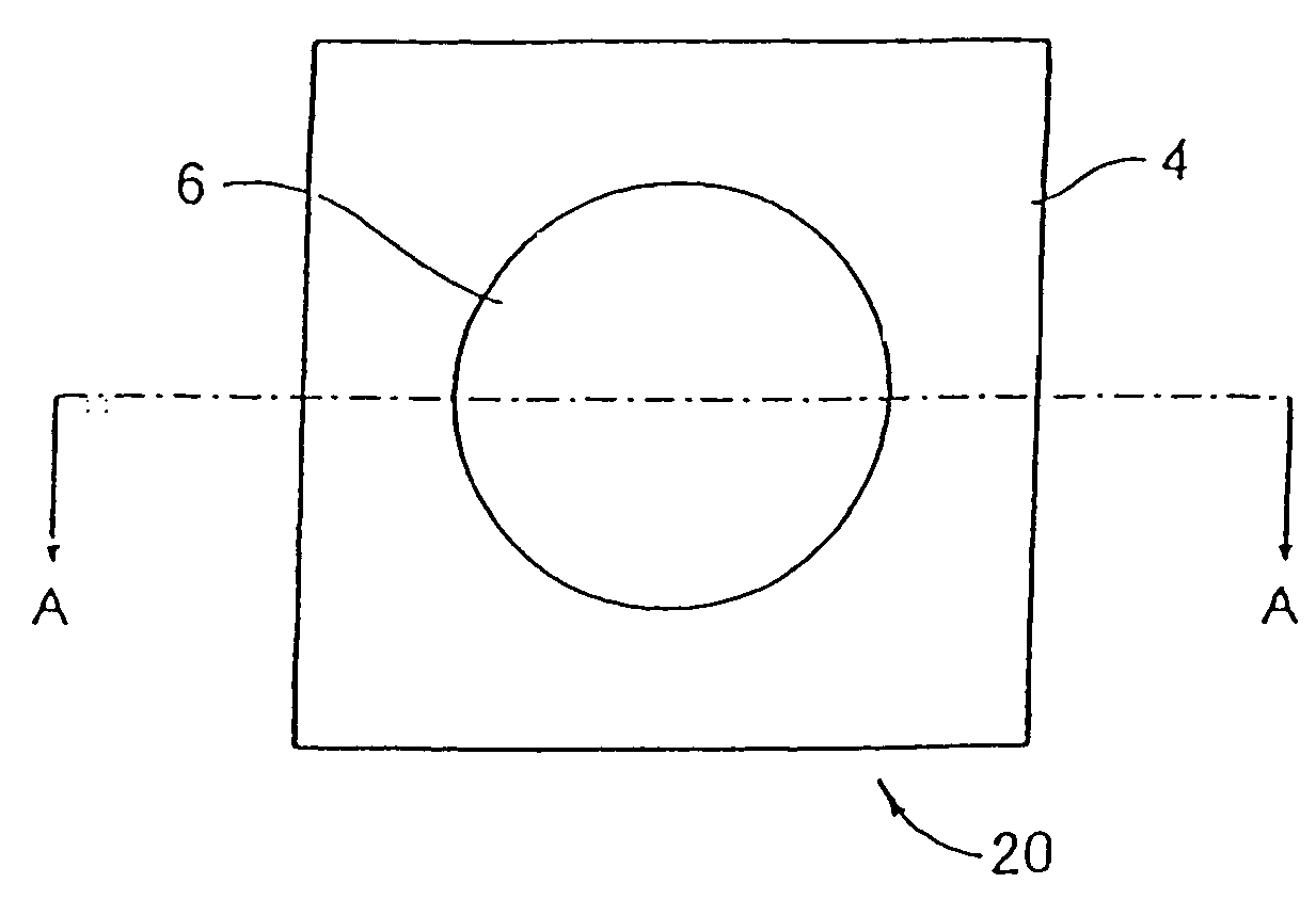
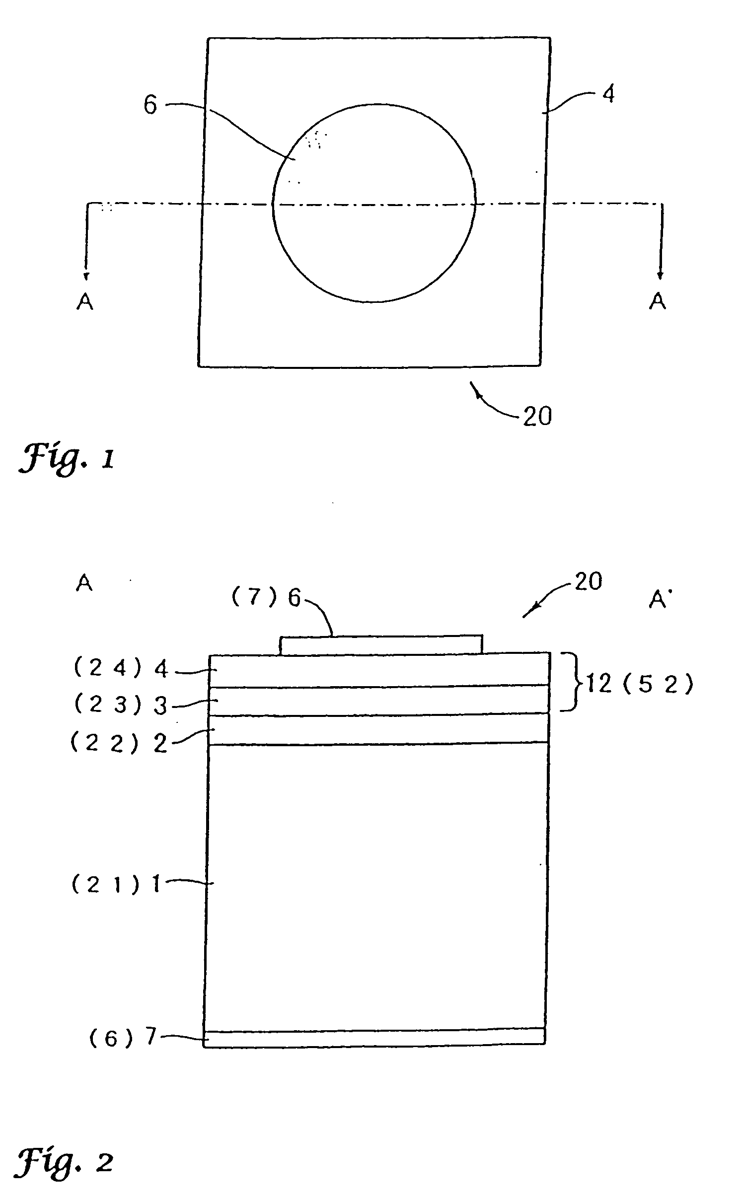
[0069] FIG. 1 is a schematic plan view of a gallium nitride (GaN)-based blue LED having a light-emitting part structure of single hetero (SH) structure containing a gallium nitride phosphide crystal layer. FIG. 2 is a schematic sectional view cut along the line A-A' of FIG. 1, showing a multilayer structure of gallium nitride (GaN)-based blue LED shown in FIG. 1.
[0070] An epitaxial multilayer structure having a light-emitting part structure 12 of single hetero-junction structure was constructed by stacking layers on the surface of a single crystal substrate 1 comprising a p-type silicon having a (100) plane azimuth and having added thereto boron (B), by respective vapor phase growth methods described in the following items (1) to (3).
[0071] (1) A low-temperature buffer layer 2 comprising Zn-doped p-type boron phosphide (BP) was deposited using a mixed gas of triethyl borane ((C.sub.2H.sub.5).sub.3B) / phosphine (PH.sub.3) / hydrogen (H.sub.2) as the starting material gas. The layer was ...
example 2
[0088] In this Example, the present invention is described by referring to a group-III nitride semiconductor light-emitting device having a light-emitting part structure of double hetero (DH) structure containing a gallium nitride phosphide single crystal layer.
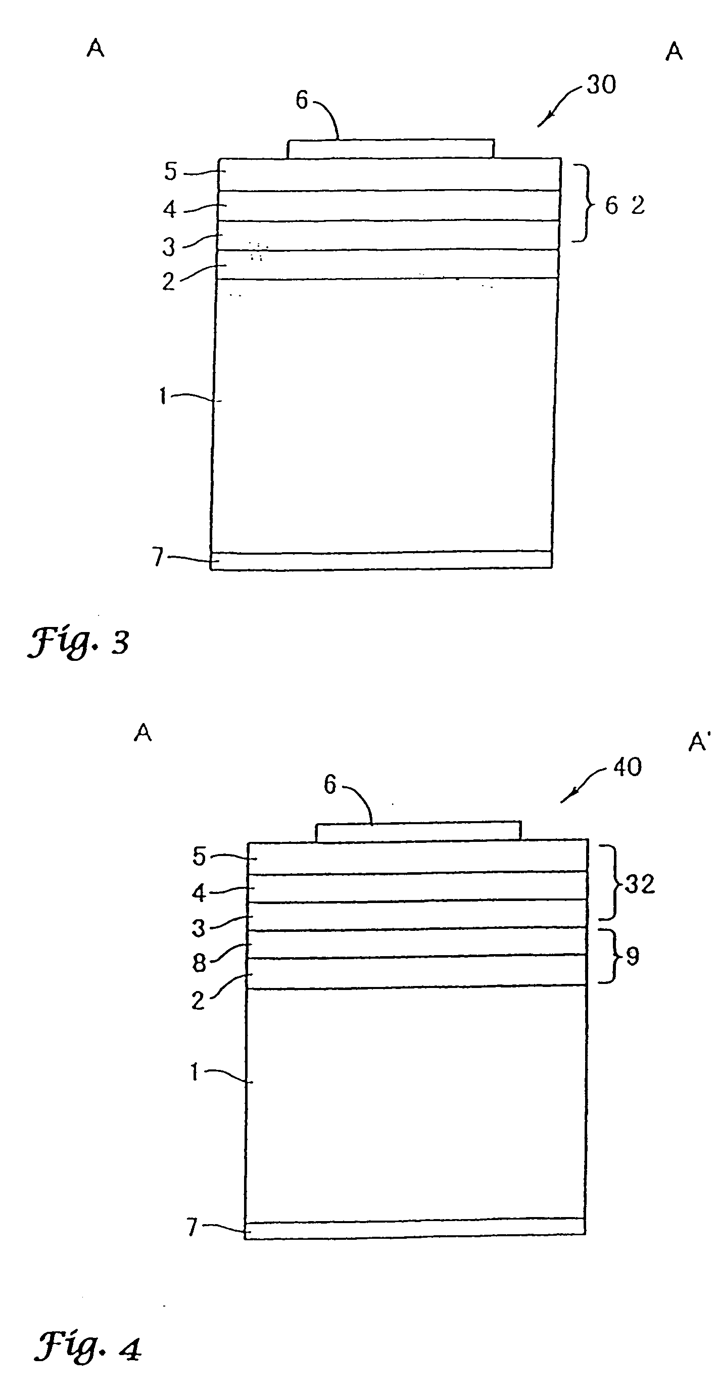
[0089] FIG. 3 is a schematic sectional view of a gallium nitride (GaN)-based blue LED fabricated based on a multilayer structure having a light-emitting part structure of DH structure according to the present invention.
[0090] In FIG. 3, the same constituent elements as in FIG. 2 are indicated by the same reference numbers and not described here.
[0091] On the same silicon single crystal substrate 1 as used in Example 1, a BP low-temperature buffer layer 2 was stacked and thereon, a lower clad layer 3 comprising GaN.sub.0.97P.sub.0.03 single crystal was stacked. On this lower clad layer, respective crystal layers described in the following items (1) and (2) were stacked to construct a multilayer structure.
[0092] (1) A light emi...
example 3
[0109] In this Example, the present invention is described by referring to a group-III nitride semiconductor blue light-emitting device having a DH junction light-emitting part structure containing a gallium nitride phosphide single crystal layer stacked on a buffer layer of a double layer structure.
[0110] FIG. 4 is a schematic sectional view of a gallium nitride-based LED fabricated based on a multilayer structure having a light-emitting part structure of DH structure according to the present invention. In FIG. 4, the same constituent elements as in FIG. 1 are indicated by the same reference numbers and not described here.
[0111] A low-temperature buffer layer 2 comprising boron phosphide (BP) was formed on a silicon single crystal substrate 1 under the growth conditions described in Example 1. On the low-temperature buffer layer 2, a crystalline buffer layer 8 comprising a zinc (Zn)-doped p-type boron phosphide (BP) crystal layer was stacked. The crystalline buffer layer 8 comprisi...
PUM
| Property | Measurement | Unit |
|---|---|---|
| thickness | aaaaa | aaaaa |
| lattice constant | aaaaa | aaaaa |
| lattice constant | aaaaa | aaaaa |
Abstract
Description
Claims
Application Information
 - R&D
- Intellectual Property
- Life Sciences
- Materials
- Tech Scout
- Unparalleled Data Quality
- Higher Quality Content
- 60% Fewer Hallucinations
Browse by: Latest US Patents, China's latest patents, Technical Efficacy Thesaurus, Application Domain, Technology Topic, Popular Technical Reports.
© 2025 PatSnap. All rights reserved.Legal|Privacy policy|Modern Slavery Act Transparency Statement|Sitemap|About US| Contact US: help@patsnap.com


