Quantum limit catalysts and hydrogen storage materials

a technology of hydrogen storage materials and catalysts, applied in the field of catalysts, can solve the problems of scarcity of fossil fuels, escalating costs, and impending energy crisis in the world, and achieve the effect of promoting the formation

Inactive Publication Date: 2005-01-20
HARNYSS IP LLC +1
View PDF18 Cites 7 Cited by
  • Summary
  • Abstract
  • Description
  • Claims
  • Application Information

AI Technical Summary

Benefits of technology

[0015] In yet another embodiment, the instant quantum limit materials are formed in a reductive chemical process. In this embodiment, one or more inorganic salts of one or more metals are combined in solution and subjected to chemical action throug

Problems solved by technology

The world is facing an impending energy crisis as the consumption of fossil fuels increases.
The dimensions of the crisis include scarcity of fossil fuels as supplies become depleted, escalating costs, confrontations over supplies, pollution and global warming.
Strong stabilizing interactions, however, precariously compete with the requirements for rapid release kinetics and release at reasonable temperatures.
Although the strong binding of hydrogen is conducive to high hydrogen storage density, strongly bound hydrogen is difficult to liberate and is therefore detrimental to the objective of achieving rapid release kinetics.
Strongly bound hydrogen can be released at reasonable rates only at

Method used


Image

  • Quantum limit catalysts and hydrogen storage materials
  • Quantum limit catalysts and hydrogen storage materials
  • Quantum limit catalysts and hydrogen storage materials

Examples


example 1

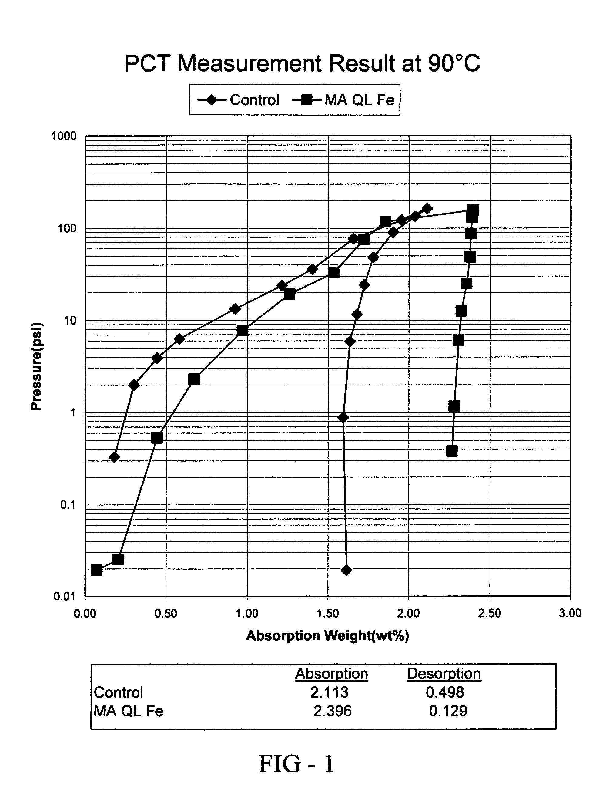
[0074] In this example, the preparation and properties of a quantum limit iron catalyst is described. The catalyst includes atomic aggregations of Fe and is prepared using sonochemical synthesis. Iron carbonyl (Fe(CO)5) was used as the iron precursor. 19.5 g of iron carbonyl was placed in 80 mL of decahydronaphthalene (Decalin) in a beaker and subjected to sonication. The iron carbonyl was protected from air and the sonication was completed in a dry box under a nitrogen atmosphere. A 750 W sonicator operating at 75% intensity was used to provide the ultrasound used in the synthesis. Sonication occurred for 8 hours using a 50% duty cycle (ultrasound was alternated on and off in equal time intervals over the 8 hours). Upon termination of the reaction, 0.5 g of quantum limit iron product was recovered. The product was analyzed using X-ray diffraction (XRD) and found to consist of aggregations of Fe having an average size of 16-20 Å.

[0075] The hydrogen absorption and desorption charact...

example 2

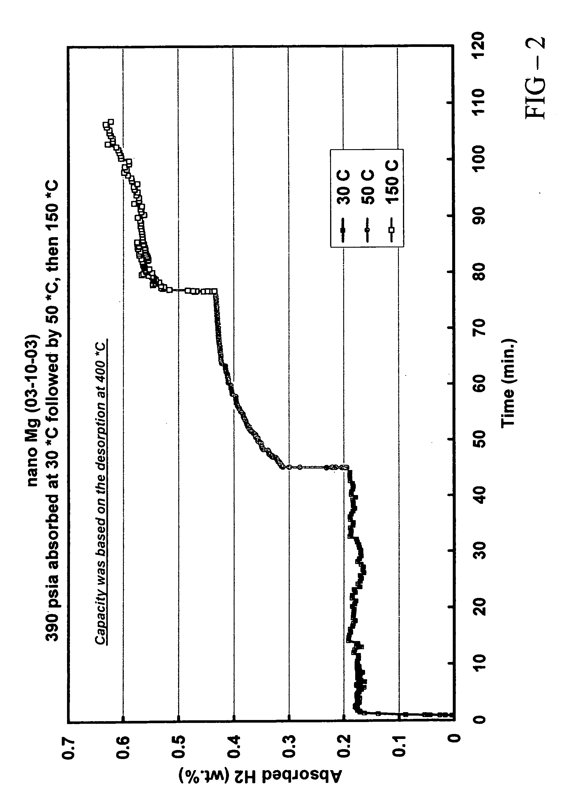
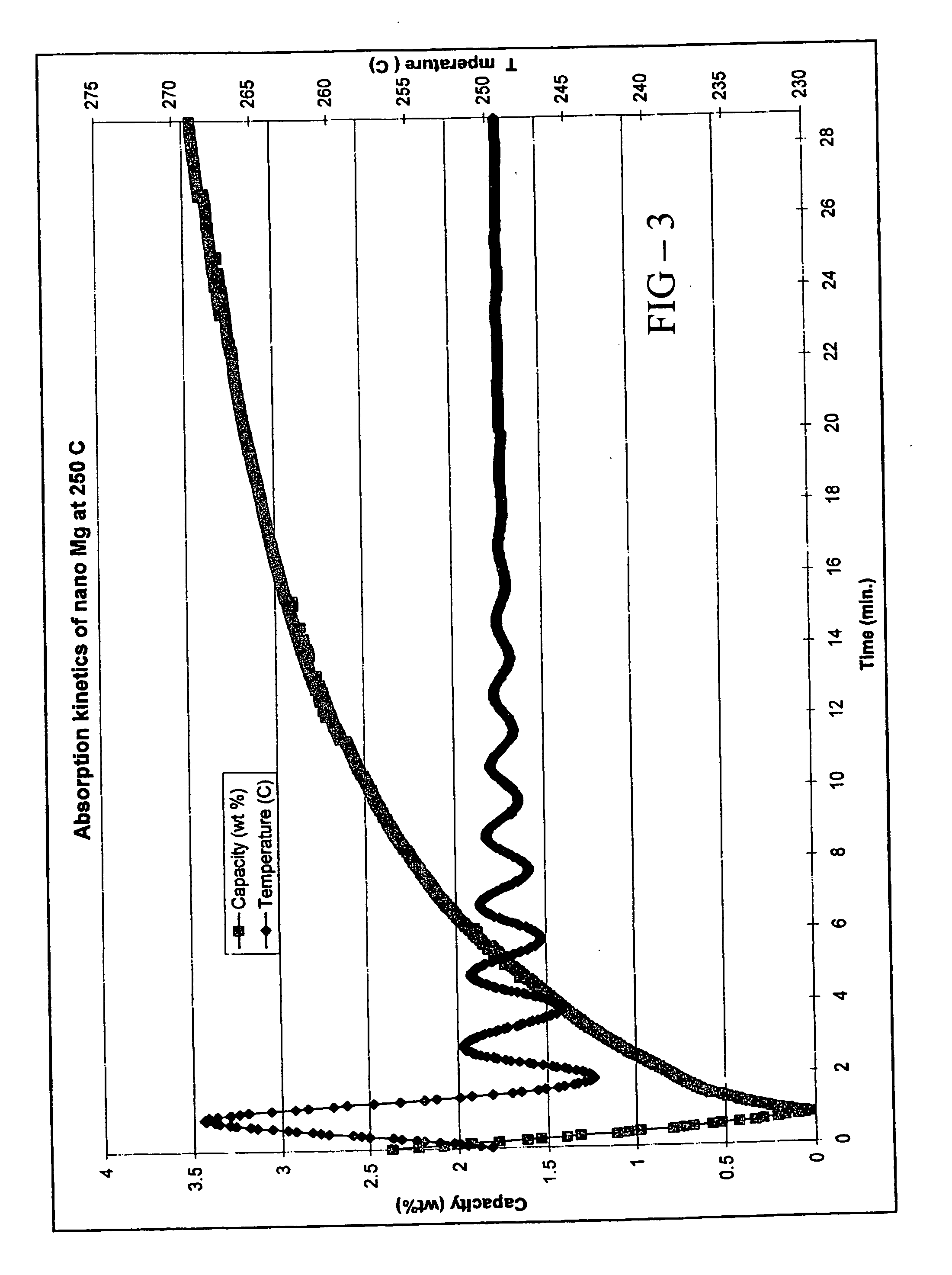
[0080] In this example, the preparation and properties of a quantum limit Mg catalyst are described. Conventional Mg is a well known hydrogen storage material that provides a particularly high hydrogen storage capacity due to strong bonds between Mg and H. The practical difficulty associated with conventional Mg is its poor hydrogen release (desorption) characteristics. Because of the high Mg-H bond strength, it is difficult to remove hydrogen from the storage sites of conventional Mg and accordingly high desorption temperatures are required.

[0081] The instant Mg catalyst was prepared through a thermal decomposition reaction. Mg(anthracene)·2THF was used as the Mg precursor. The precursor was an orange solid. 5.8 g of the precursor were sublimed under vacuum. At a temperature of ca. 40° C., the THF was liberated from the precursor and at a temperature of ca. 150° C., anthracene was sublimed to leave a fine Mg black powder. Analysis of the sublimation process indicated that 2.2 g an...

example 3

[0084] In this example, the preparation of a quantum limit V catalyst is described. An organometallic vanadium precursor, V(Cp)(CO)4 (Cp=cyclopentadienyl) is used in the preparation. 4.963 g of the vanadium precursor were placed in decane and refluxed until a black precipitate was formed. The precipitate was analyzed to be V and XRD and SEM analysis showed that the product consisted of aggregations of V having an average size of 40 Å.


PUM

PropertyMeasurementUnit
Temperatureaaaaaaaaaa
Percent by massaaaaaaaaaa

Abstract

A quantum limit catalyst. The quantum limit corresponds to a size domain in which material properties are no longer constrained by the structure and bonding requirements imposed by the macroscopic length scale. The instant quantum limit catalyst is comprised of atomic aggregations whose dimensions correspond to the quantum limit. In the quantum limit, the atomic aggregations acquire structural configurations and electronic interactions not attainable in the macroscopic limit. The structural configurations possible in the quantum limit correspond to atomic aggregations having bond lengths, bond angles, topologies and coordination environments that differ from those found in the macroscopic limit. The electronic interactions possible in the quantum limit originate from wavefunction overlap and tunneling between atoms and lead to modifications in the magnitude and/or spatial distribution of electron density at catalytic sites to provide improved catalytic properties. The modifications in electron density and wavefunction characteristics (overlap and directionality) achieved in the quantum limit provide, in effect, “new” or “virtual” chemical elements whose structure and bonding deviate from those associated with the “standard” chemical elements of conventional materials. Combinations of virtual elements provide virtual alloys having structures and properties not available in conventional alloys. Representative quantum limit catalysts include materials comprised of quantum scale atomic aggregations of metal atoms. The aggregations include one or more metals and have sizes in the angstrom scale range. Examples including catalysts derived from Fe, Mg, V and Co are disclosed. Catalytic properties are exemplified in the context of hydrogen storage. Methods that may be used to prepare quantum limit catalysts include sonochemical synthesis, thermal decomposition, and reduction.

Description

RELATED APPLICATION INFORMATION [0001] This application is a continuation-in-part of U.S. patent application Ser. No. 10 / 623,939 entitled “Supported Catalyst having Electronic Interaction between Catalytic Phase and Support Matrix” and filed on Jul. 18, 2003; the disclosure of which is incorporated by reference herein.FIELD OF INVENTION [0002] This invention pertains to catalysts comprised of atomic aggregations having length scales in the quantum regime. More particularly, this invention relates to catalysts having catalytic sites whose catalytic properties result from quantum mechanically induced modifications of electron density originating from wavefunction overlap. Most particularly, this invention relates to hydrogen storage materials having hydrogen storage sites with binding energies for atomic hydrogen that provide high hydrogen storage densities as well as favorable hydrogen release rates at temperatures only modestly above room temperature. BACKGROUND OF THE INVENTION [00...

Claims


Application Information

Patent Timeline
IPC IPC(8): B01J23/02B01J23/22B01J23/74B01J23/745B01J23/75B01J35/00B01J37/08B01J37/34C01B3/00
CPCB01J23/02B01J23/22B01J23/74B01J23/745B01J23/75Y02E60/327B01J35/002B01J37/086B01J37/343C01B3/0026C01B3/0031B01J35/0013B01J35/006Y02E60/32
Inventor OVSHINSKY, STANFORD R.
Owner HARNYSS IP LLC
Why Eureka
Try Eureka