Method of manufacturing a wiring substrate and an electroless copper plating solution for providing interlayer connections

a manufacturing method and technology of wiring substrate, applied in the direction of resistive material coating, superimposed coating process, liquid/solution decomposition chemical coating, etc., can solve the problem of increasing the aspect ratio of the via-hole, it is difficult to uniformly perform metal plating within such via-holes, etc., and achieve good reproducibility

Inactive Publication Date: 2005-02-24
HITACHI LTD
View PDF5 Cites 4 Cited by
  • Summary
  • Abstract
  • Description
  • Claims
  • Application Information

AI Technical Summary

Benefits of technology

[0019] Practically, the above-noted electroless copper plating solution is used to apply electroless copper plating to a wiring structure which includes more than one opening having on a dielectric body surface an ultrafine diameter φ ranging from 50 to 150 μm and a closed bottom portion deeper than such diameter, i.e. whose depth is greater in value than its width, thereby enabling fabrication of a continuous copper layer with an almost uniform thickness on or over sidewall and bottom surfaces within the opening and the dielectric body surface. This in turn makes it possible to manufacture with good reproducibility the intended wiring substrate wherein the thickness of a copper layer on the sidewall / bottom surfaces within the micro-opening of aspect ratios ranging from 1.0 to 2.0 is greater than 0.9 times that of a copper layer overlying the dielectric body surface.

Problems solved by technology

In cases where plating is applied to one-side closed via-holes for achievement of an intended electrical interlayer connection, it becomes more difficult to uniformly perform metal plating within such via-holes with an increase in via-hole aspect ratios.
This difficulty might often serve as a serious bar or“process bottle-neck” in the manufacture of highly integrated parts-mount substrates.

Method used


Image

  • Method of manufacturing a wiring substrate and an electroless copper plating solution for providing interlayer connections
  • Method of manufacturing a wiring substrate and an electroless copper plating solution for providing interlayer connections
  • Method of manufacturing a wiring substrate and an electroless copper plating solution for providing interlayer connections

Examples


embodiment 1

[0059] While employing copper sulfate as a copper ion source and formalin as a copper ion reducing agent, electroless copper plating was performed, with sodium hydroxide being used as pH adjuster.

[0060] Presented below is the composition of a plating liquid or solution along with several plating process conditions.

Plating Solution Composition:copper sulfate pentahydrate0.04 mol / lethylene-diaminetetraacetic acid 0.1 mol / lformaldehyde0.03 mol / lsodium hydroxide0.01 mol / lmandelonitrile0.0005 mol / l 

[0061] Note here that the concentration of sodium hydroxide was appropriately adjusted so that pH=12.3 on a case-by-case basis.

Plating Conditions:pH12.3liquid temperature70° C.

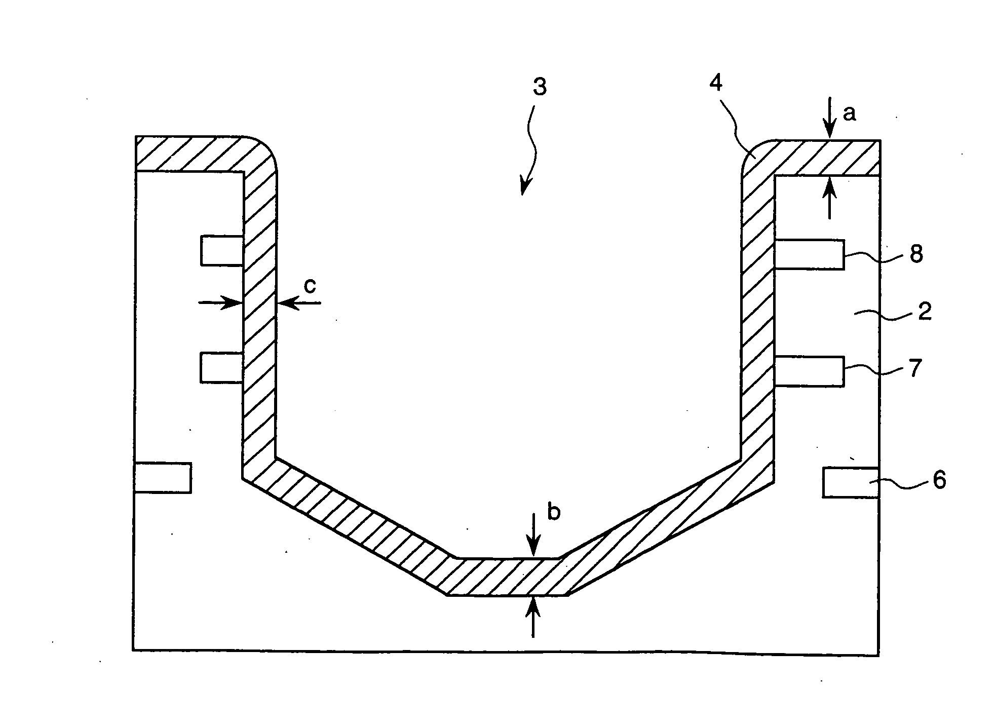
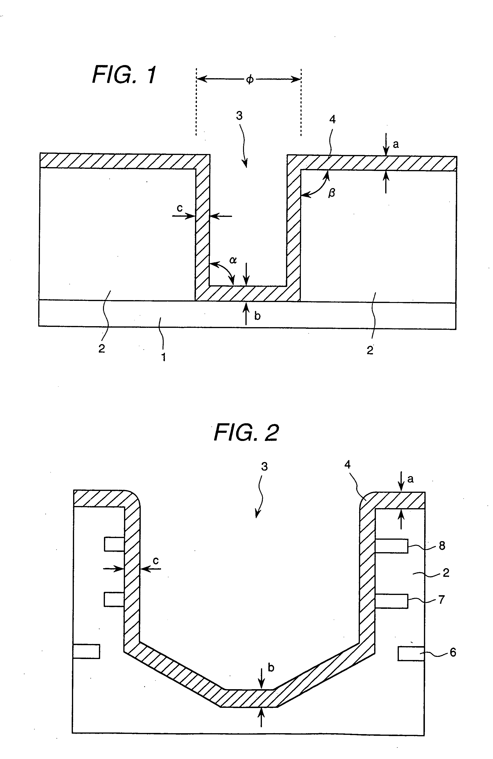
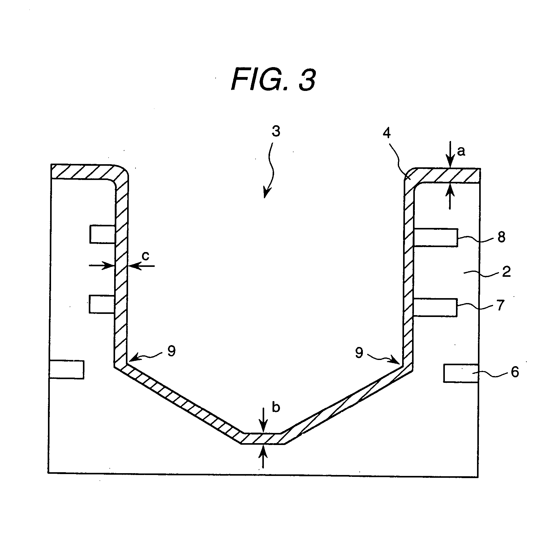
[0062] Using the electroless copper plating solution, plating was applied to more than one via-hole formed on a test substrate; then, the resulting uniformity of deposition to inner wall faces of a via-hole was evaluated by profile observation. This test substrate was fabricated by a method that will be described be...

embodiment 3

[0079] The composition of a plating solution used in this embodiment, along with plating process conditions are set forth below.

Plating Solution Composition:copper sulfate pentahydrate0.04 mol / lethylene-diaminetetraacetic acid 0.1 mol / lformaldehyde0.03 mol / lsodium hydroxide0.01 mol / ltriethylenetetramine0.02 mol / l

[0080] Note that the concentration of sodium hydroxide was appropriately adjusted so that pH=12.3 was established.

Plating Conditions:pH12.3liquid temperature70° C.

[0081] The deposition uniformity and plated film's physical properties were evaluated by using a test substrate and a method of fabricating a physical property measuring plated film, plus a deposition uniformity evaluation method, all of which are similar to those in Embodiment 1 stated above. The resultant plating rate with use of the plating solution of this embodiment was 4.3 μm / h. Plating was applied to the top surface of the test substrate for 6 hours, thereby forming a plated film with a thickness of abou...

embodiment 4

[0084] The composition of a plating solution used in this embodiment, along with plating process conditions, are set forth below.

Plating Solution Composition:copper sulfate pentahydrate0.04 mol / lethylene-diaminetetraacetic acid 0.1 mol / lformaldehyde0.03 mol / lsodium hydroxide0.01 mol / lmandelonitrile0.0005 mol / l 2,2′-bipyridyl0.0002 mol / l 

[0085] Note that the concentration of sodium hydroxide was appropriately adjusted so that pH=12.5 was established.

Plating Conditions:pH12.5liquid temperature74° C.

[0086] The deposition uniformity and plated film's physical properties were evaluated by using a test substrate and a method of fabricating a physical property measuring plated film, plus a deposition uniformity evaluation method, all of which are similar to those in Embodiment 1 stated above. The resultant plating rate with use of the plating solution of this embodiment was 5.1 μm / h. Plating was applied to the top surface of the test substrate for 5 hours, thereby forming a plated film...


PUM

PropertyMeasurementUnit
diameteraaaaaaaaaa
aspect ratioaaaaaaaaaa
thicknessaaaaaaaaaa

Abstract

A multilayer wiring substrate which is high in connection reliability is provided through process steps of forming more than one opening, such as a via-hole in a dielectric layer laminated on a substrate, and then applying uniform copper plating to a surface portion of the dielectric layer including the opening to thereby form a wiring layer. An electroless copper plating solution with at least one of mandelonitrile and triethyltetramine mixed therein is used to perform the intended electroless copper plating. An alternative process makes use of an electroless copper plating solution with chosen additives or “admixtures” containing at least on of mandelonitrile and triethyltetramine plus eriochrome block T along with at least one of 2,2′-bipyridyl, 1,10-phenanthroline, and 2,9-dimethyl-1,10-phenanthroline

Description

BACKGROUND OF THE INVENTION [0001] The present invention relates in general to wiring substrates; and, more particularly, the invention relates to a multilayer wiring substrate comprising a copper layer formed at a fine or “micro” opening such as via-hole, for interconnection between a plurality of wiring leads, to a method of manufacture thereof, and to an electroless copper plating solution used in the method. [0002] Currently available electroless copper plating solutions contain copper ions, a complexing agent of copper ions, a reducing agent of the copper ions, and a pH adjuster. Such solutions further contain an additive agent mixed thereinto for purposes of improving the mechanical characteristics of a plated film(s) or, alternatively, for improving the stability of the plating solution. [0003] One typical electroless copper plating solution containing these additive agents is disclosed, for example, in JP-A-51-105932 (1976). The plating solution taught by this Japanese docum...

Claims


Application Information

Patent Timeline
Patent Type & Authority Applications(United States)
IPC IPC(8): H05K1/02C23C18/38C23C18/40H05K3/18H05K3/42H05K3/46
CPCC23C18/40H05K3/421H05K2201/09518H05K3/426H05K3/429H05K3/422C23C18/38
Inventor ITABASHI, TAKEYUKIAKAHOSHI, HARUOTAKAI, EIJINISHIMURA, NAOKIIIDA, TADASHIUEDA, YOSHINORI
Owner HITACHI LTD
Why Eureka
Try Eureka