
Element-specific X-ray fluorescence microscope and method of operation

a fluorescence microscope and element-specific technology, applied in the direction of instruments, material analysis using wave/particle radiation, nuclear engineering, etc., can solve the problems of limiting throughput and unpractical element-specific imaging systems using laboratory x-ray sources, and achieves high signal to noise and better elemental specificity

Inactive Publication Date: 2005-05-26
CARL ZEISS X RAY MICROSCOPY
View PDF16 Cites 9 Cited by
  • Summary
  • Abstract
  • Description
  • Claims
  • Application Information

AI Technical Summary

Benefits of technology

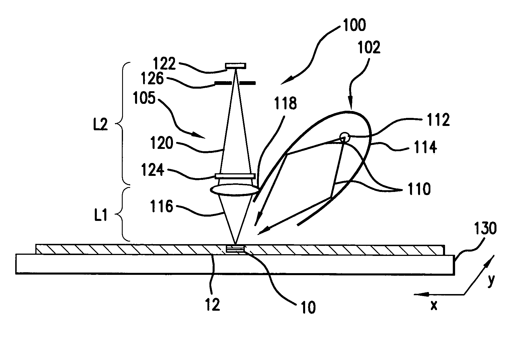
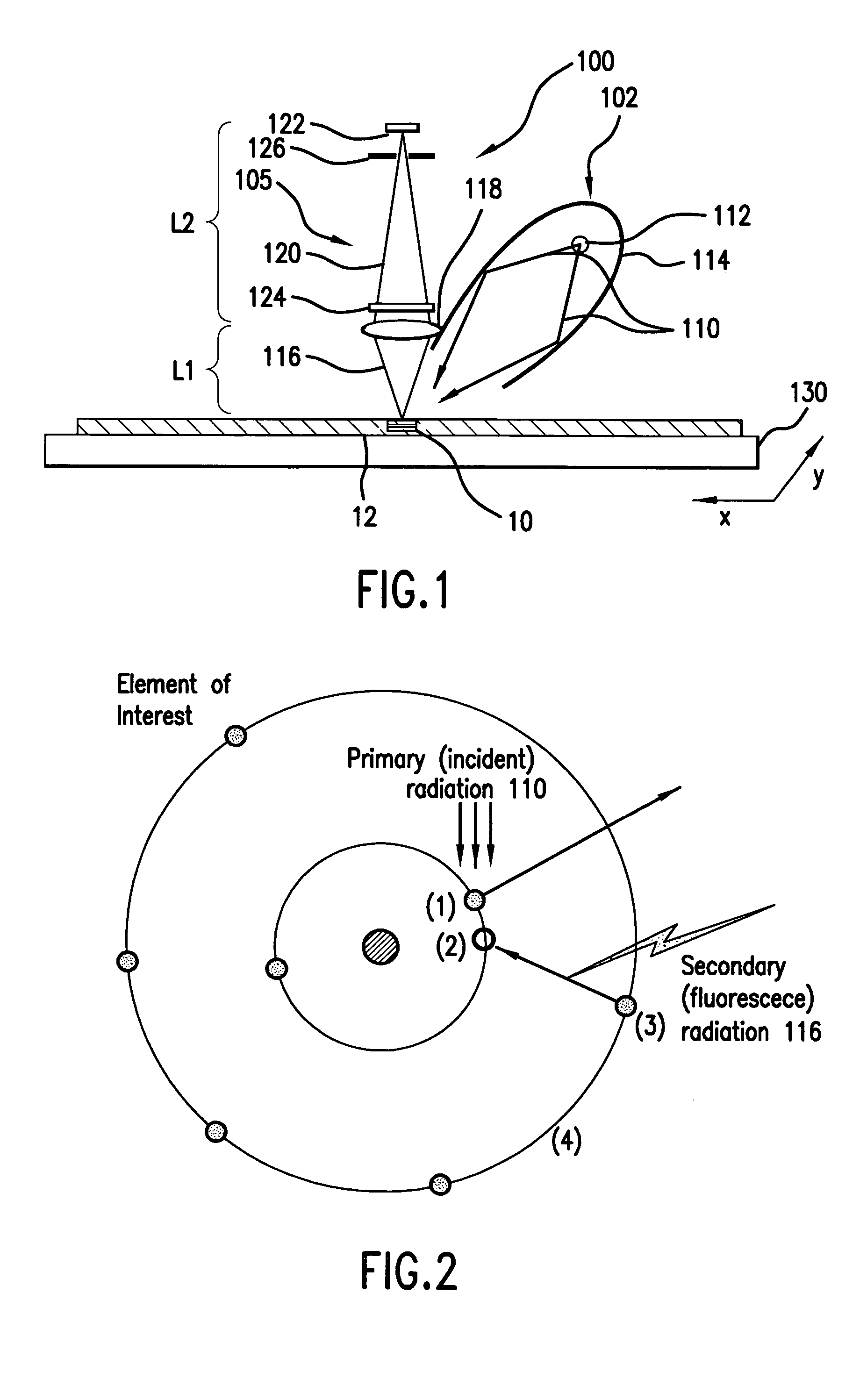
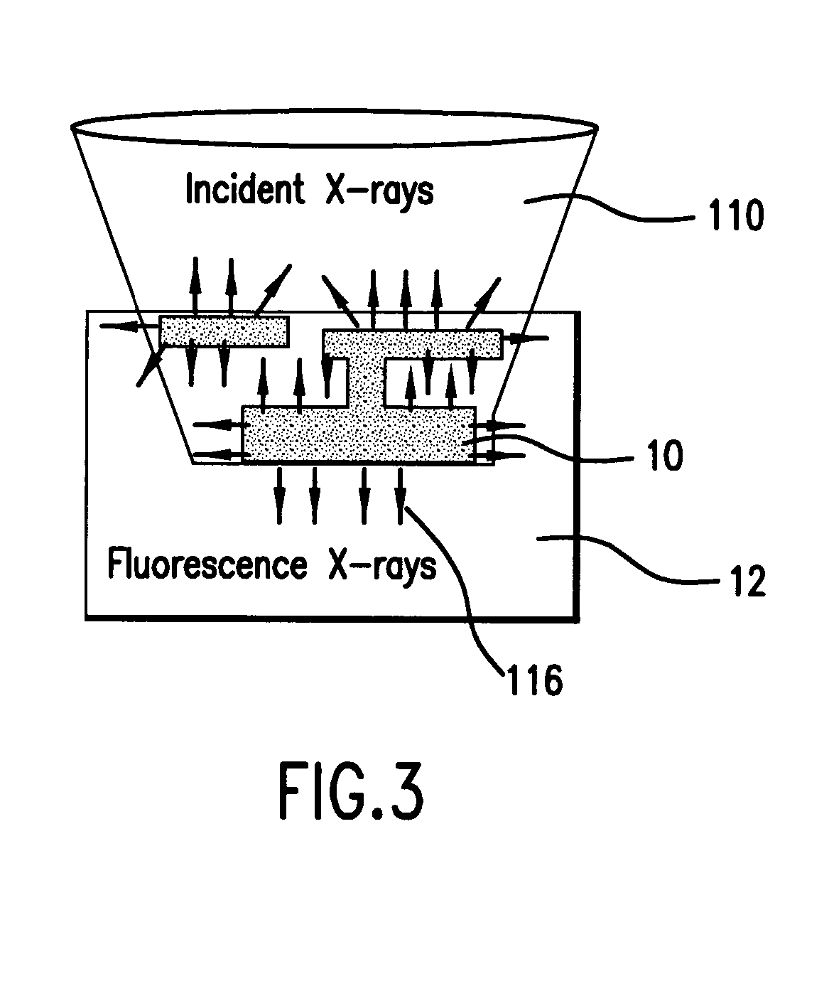
[0009] This embodiment of the present invention relies on both the imaging and chromatic properties of the chromatic lens to image an element of interest in a test object by appropriately configuring the imaging system to form images on the detector array of the characteristic fluorescence X-rays from the test object. A given element in the test sample can be imaged using its fluorescence X-rays. If a zone plate is used as the chromatic lens, the preferential imaging of the element can be enhanced if the plate itself is made of a compound including the same element. For example, when imaging copper using the Cu Lα spectral line, a copper zone plate lens is used. This enhances the preferential imaging of the zone plate lens because its diffraction efficiency (percent of incident energy diffracted into the focus) changes rapidly near an absorption line and can be made to peak at the X-ray fluorescence line of the element from which it is fabricated.
[0011] Wavelength dispersive elements can be used in the optical train between the object of interest and the detector to improve preferential imaging.
[0014] It is recognized that element-specific imaging using a zone plate's high order diffraction, such as the 3rd order diffraction, offers significantly better elemental specificity than using the primary 1st order diffraction. Generally, a zone plate's focusing efficiency for higher order diffraction is smaller than the primary 1st order diffraction.
[0015] A central stop on the zone plate may be required or desirable to obtain high signal to noise in the image formed on the detector by the fluorescence x-rays of interest by reducing or eliminating the x-rays photons that are not focused by the zone plate.
[0022] It is recognized that the test object can be illuminated with an illumination beam with a large solid angle for increasing the rate of the secondary x-ray fluorescence generation. It is further recognized that the throughput of the x-ray fluorescence microscope can be improved by optimization of the illumination system, which typically comprises the source and the condenser, to increase the production rate of the secondary fluorescence x-rays within the volume of interest in the test object. An example of such a design includes a fine focus x-ray source specifically designed for high brightness applications and an x-ray condenser specifically designed for collecting primary ionizing x-rays from the source over a large solid angle and directing them onto the test object.

Problems solved by technology

Element specific imaging with a spatial resolution approaching 100 nanometers (nm) has been demonstrated with high elemental sensitivity using a high brightness synchrotron radiation source, but the serial nature of the raster scanning significantly limits the throughput and the high source brightness requirement makes it unpractical for producing an element-specific imaging system using a laboratory x-ray source.

Method used


Image

  • Element-specific X-ray fluorescence microscope and method of operation
  • Element-specific X-ray fluorescence microscope and method of operation
  • Element-specific X-ray fluorescence microscope and method of operation

Examples


examples

[0076] The X-ray fluorescence from important materials of an IC are induced with radiation energy in the approximately 100 to 8000 eV range. The materials that produce the x-ray fluorescence are copper at 930 eV (La) and 8046 eV (Ka), silicon at 99 eV (La) and 1740 eV (Ka), germanium at 1186 eV (La), tantalum at 1710 eV (Ma), titanium at 452 eV (La) and 4510 eV (Ka), cobalt at 776 eV (La) and 6929 eV (Ka), phosphorus at 2013 eV (Ka), arsenic at 1282 eV (La), and aluminum at 1486 eV (Ka), for example. Boron at 183 eV (Ka) is another alterative.

[0077] Considering copper as an example, FIG. 4 shows the efficiency of a 500 nanometer (nm) copper zone plate in the 900 to 950 eV range, where copper has a fluorescence line. Note that the efficiency peaks to about 30% around 932 eV, which is close to the energy of a Cu La fluorescence line at 930 eV.

[0078]FIG. 5 shows the transmission of copper over this 900 to 950 eV range. For example, 200 nm of copper has a transmission above 933 eV of ...


PUM

PropertyMeasurementUnit
grazing incidence angleaaaaaaaaaa
solid angleaaaaaaaaaa
atomic numbersaaaaaaaaaa

Abstract

An element-specific imaging technique utilizes the element-specific fluorescence X-rays that are induced by primary ionizing radiation. The fluorescence X-rays from an element of interest are then preferentially imaged onto a detector using an optical train. The preferential imaging of the optical train is achieved using a chromatic lens in a suitably configured imaging system. A zone plate is an example of such a chromatic lens; its focal length is inversely proportional to the X-ray wavelength. Enhancement of preferential imaging of a given element in the test sample can be obtained if the zone plate lens itself is made of a compound containing substantially the same element. For example, when imaging copper using the Cu La spectral line, a copper zone plate lens is used. This enhances the preferential imaging of the zone plate lens because its diffraction efficiency (percent of incident energy diffracted into the focus) changes rapidly near an absorption line and can be made to peak at the X-ray fluorescence line of the element from which it is fabricated. In another embodiment, a spectral filter, such as a multilayer optic or crystal, is used in the optical train to achieve preferential imaging in a fluorescence microscope employing either a chromatic or an achromatic lens.

Description

RELATED APPLICATIONS [0001] This application is a Divisional of U.S. application Ser. No. 10 / 157,089, filed May 29, 2002 which is incorporated herein by reference in its entirety.BACKGROUND OF THE INVENTION [0002] A number of techniques exist for the elemental analysis of objects using X-rays. Some of these techniques rely on the different X-ray attenuation characteristics of elements, whereas others rely on X-ray fluorescence. [0003] An example of an attenuation-based analysis technique utilizes characteristic elemental resonance energies. The attenuation of an X-ray beam of a sufficiently narrow spectral bandwidth increases substantially, when the central energy increases over the resonance energy of a constituent element of a test object. X-ray microscopes taking advantage of this characteristic have been developed for element-specific imaging. The microscopes typically combine a source, such as a synchrotron, a monochromator, a lens, such as a zone plate lens, a detector array, ...

Claims


Application Information

Patent Timeline
Patent Type & Authority Applications(United States)
IPC IPC(8): G01N23/223G01N23/225G21K1/06G21K3/00G21K7/00H01J37/12H01J37/244
CPCB82Y10/00G01N2223/076G21K1/062G01N23/223G01N23/00
Inventor YUN, WENBINGNILL, KENNETH W.
Owner CARL ZEISS X RAY MICROSCOPY
Learn More