
Method of producing insulator thin film, insulator thin film, method of manufacturing semiconductor device, and semiconductor device

a technology of insulator and thin film, which is applied in the direction of solid-state devices, coatings, chemical vapor deposition coatings, etc., can solve the problems of increasing the leak current between the gate and the substrate, the limit of thinning the gate oxide film, and the low heat resistance of the gate, so as to and reduce the concentration of metal atoms

Active Publication Date: 2005-06-02
SONY CORP
View PDF4 Cites 13 Cited by
  • Summary
  • Abstract
  • Description
  • Claims
  • Application Information

AI Technical Summary

Benefits of technology

[0007] It is an object of the present invention to provide an insulator thin film with which is it possible to reduce immobile electric charges at the interface of a substrate and an electrode, and to restrain punch-through of boron without an increase in interface level, thereby forming a MOSFET free of Vth shift and mobility degradation.
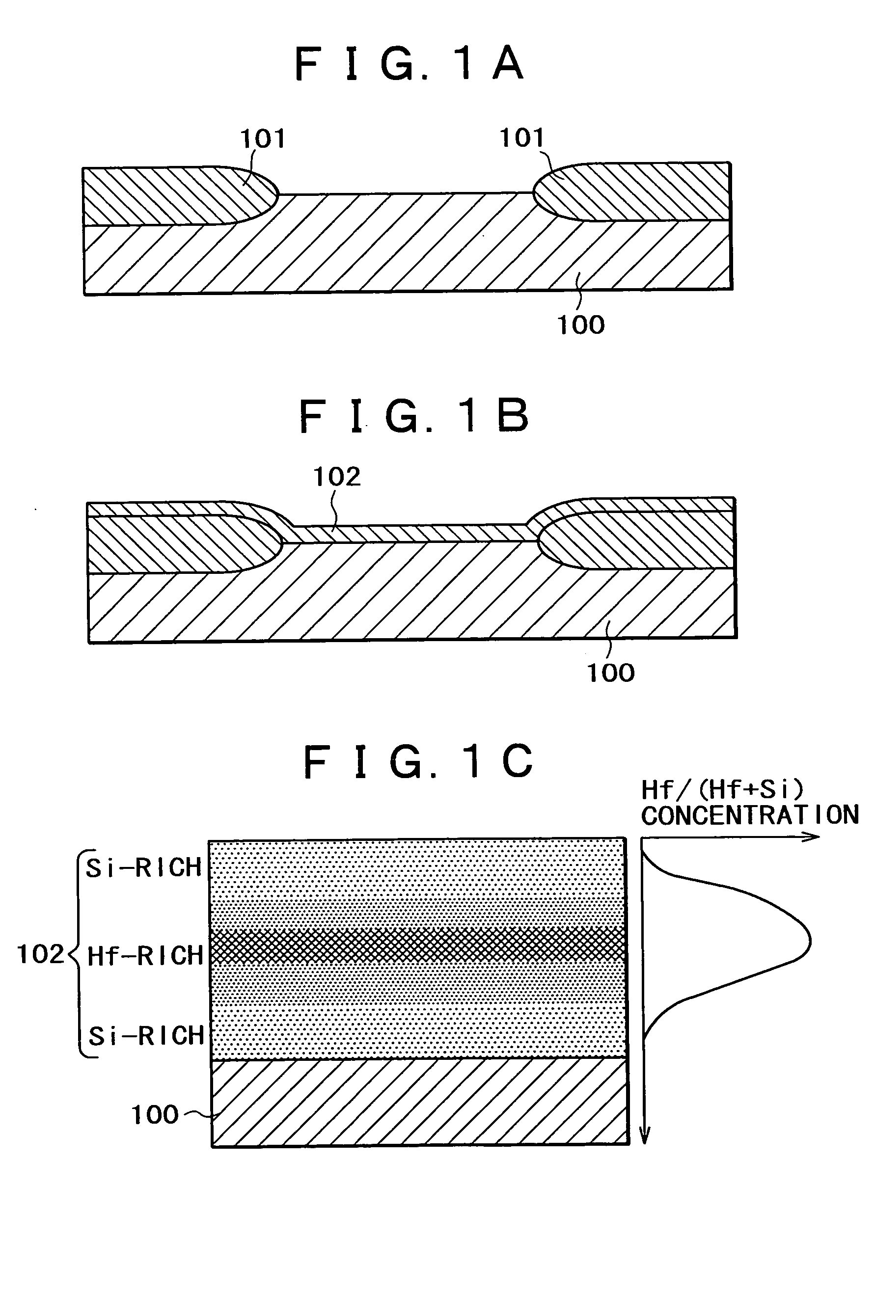
[0012] The method of producing an insulator thin film and the insulator thin film according the present invention includes, and is formed by, a first step of forming a silicon atomic layer on a substrate and forming an oxygen atomic layer on the silicon atomic layer, by the atomic layer deposition process, and a second step of forming a metal atomic layer on the substrate and forming an oxygen atomic layer on the metal atomic layer, by the atomic layer deposition process. Therefore, a silicon oxide film and a metal oxide film can be formed in a thickness of one atomic layer. In addition, by controlling the number of times the first step and the second step are carried out, the insulator thin film can be formed in the condition where the concentration of metal atoms has a gradient. Therefore, it is possible to ensure that no metal atom is contained at the interface of the insulator thin film, or to extremely reduce the concentration of the metal atoms. Accordingly, a high dielectric constant film can be formed to be thick, so that, in the insulator thin film formed by the method of producing an insulator thin film according to the present invention, punch-through of boron would not occur, and, in the case where the method is applied to a gate insulation film of a MOSFET, a favorable high dielectric constant film free of Vth shift and mobility degradation can be obtained advantageously.

Problems solved by technology

One of the walls is the limitation in thinning the gate oxide film of a transistor.
In the case of such a film thickness, there is probably generated the problem that direct tunneling of carriers through the film would occur, resulting in an increase of leak current between the gate and the substrate.
However, the high dielectric constant films (also called high-k films) of ZrO2, HfO2 and the like are low in heat resistance, are liable to undergo crystallization, and are liable to undergo a siliciding reaction with the silicon (Si) substrate, with the result of an increase in the leak current.
A problem to be solved lies in that, in the case of forming a high-k film according to the related art, immobile electric charges are generated at the boundaries between the high-k film and the Si substrate and the poly-Si electrode, resulting in a shift of threshold voltage (Vth) and mobility degradation.
Another problem to be solved lies in that, in PMOS transistors, boron with which the gate electrode is doped would, upon the subsequent heat treatment, punch through the high dielectric constant film so as to diffuse to the substrate side.

Method used


Image

  • Method of producing insulator thin film, insulator thin film, method of manufacturing semiconductor device, and semiconductor device
  • Method of producing insulator thin film, insulator thin film, method of manufacturing semiconductor device, and semiconductor device
  • Method of producing insulator thin film, insulator thin film, method of manufacturing semiconductor device, and semiconductor device

Examples


embodiment 1

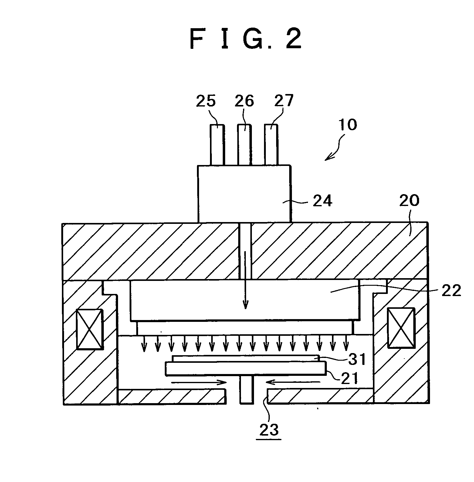
[0024] As shown in FIG. 2, a thin film forming system 10 includes a chamber 20. The chamber 20 is equipped with an external heater (not shown), and the chamber 20 is heated by the heater. A stage (susceptor) 21 for mounting thereon a substrate 3 on which to form an insulator thin film is provided in the inside of the chamber 20. A shower head 22 for supplying raw material gases is provided at a position opposite to the substrate mount surface of the stage 21. An exhaust port 23 for discharging the raw material gases in the chamber 20 is provided at a bottom portion of the chamber 20, and the exhaust port 23 is connected to an evacuation system (not shown). The shower head 22 is provided with a gas inlet port 23 and a gas selector valve 24, in this order from the interior side of the chamber 20. Supply pipes 25, 26, 27 for supplying, for example, a first raw material gas, a second raw material gas and a purging inert gas are connected to the gas selector valve 24. While the number of...

embodiment 2

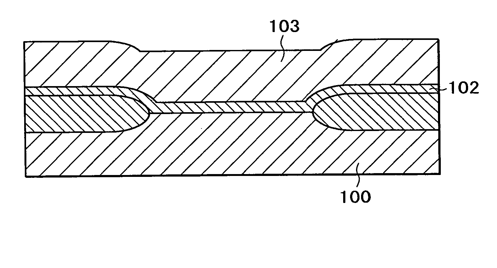
[0040] Next, one embodiment of the method of manufacturing a semiconductor device and the semiconductor device according to the present invention will be described referring to the manufacturing process diagrams in FIGS. 5A to 5C. FIGS. 5A to 5C illustrate one example of a semiconductor device in which the insulator thin film formed by the method of producing an insulator thin film in Embodiment 1 described above referring to FIGS. 1A to 1C is used as a gate insulation film, i.e., an insulated gate type field effect transistor.

[0041] As shown in FIG. 5A, an insulator thin film 102 is formed on a substrate (silicon substrate) 100 according to Embodiment 1 above. Next, a gate electrode material film 103 is formed on the insulator thin film 102. Polycrystalline silicon (polysilicon), for example, can be used for the gate electrode material film, and the chemical vapor deposition process can be used as one example of the film forming method. The film thickness was, for example, 180 nm....


PUM

PropertyMeasurementUnit
Concentrationaaaaaaaaaa

Abstract

A method of producing an insulator thin film, for forming a thin film on a substrate by use of the atomic layer deposition process, includes a first step of forming a silicon atomic layer on the substrate and forming an oxygen atomic layer on the silicon atomic layer, and a second step of forming a metal atomic layer on the substrate and forming an oxygen atomic layer on the metal atomic layer, wherein the concentration of the metal atoms in the insulator thin film is controlled by controlling the number of times the first step and the second step are carried out.

Description

BACKGROUND OF THE INVENTION [0001] The present invention relates to a method of producing an insulator thin film, an insulator thin film formed by the producing method, a method of manufacturing a semiconductor device using the insulator thin film, and a semiconductor device, with which it is easy to freely control the concentration gradient of a metal in a film. [0002] Miniaturization of MOS transistors have already been coming to a gate length of 0.1 μm. The miniaturization leads to a further enhancement of operating speed of devices, a further reduction in electric power consumption, and a further reduction in the area occupied by the device. Recently, in addition, it has become possible to mount a larger number of devices per a fixed chip area, and it has therefore been realized to increase the number of functions of LSIs themselves. However, the pursuit of miniaturization is expected to be encountered by large walls, with the 0.1 μm rule as a boundary. One of the walls is the l...

Claims


Application Information

Patent Timeline
IPC IPC(8): H01L21/316C23C16/40C23C16/44C23C16/455H01L21/205H01L21/28H01L21/31H01L21/314H01L21/336H01L29/51H01L29/78
CPCC23C16/401C23C16/45529H01L21/28202H01L21/3142H01L21/31608H01L21/31645H01L2924/0002H01L29/513H01L29/517H01L29/518H01L2924/00H01L21/0228H01L21/02164H01L21/02181H01L21/02274H01L21/02107H01L21/02321H01L21/02329H01L21/0234
Inventor HIRANO, TOMOYUKI
Owner SONY CORP
Learn More