
Organic light-emitting display device

a display device and organic technology, applied in the direction of organic semiconductor devices, printing,filing appliances, etc., can solve the problems of unavoidable light emission voltage rise, oxidation of organic films, and elevated light emission voltag

Active Publication Date: 2005-09-29
SAMSUNG DISPLAY CO LTD +1
View PDF17 Cites 15 Cited by
  • Summary
  • Abstract
  • Description
  • Claims
  • Application Information

AI Technical Summary

Benefits of technology

[0010] An object of the present invention is to provide a top emission type organic light-emitting display device in a production of which it is possible to prevent the organic layers from being oxidized in the step of forming the upper transparent electrode and which is capable of emitting light at a low voltage.
[0022] The electron injection layer is intended to enhance the efficiency of electron injection from the cathode to the electron transport layer. It is preferably made of lithium fluoride, magnesium fluoride, calcium fluoride, strontium fluoride, barium fluoride, magnesium oxide or aluminum oxide. Of course the materials usable for this layer are not limited to those mentioned above, and two or more of them can be used simultaneously.
[0034] In the upper electrode film forming operation, the oxide used as the upper electrode material is partially decomposed and the generated oxygen radicals act to oxidize the organic film to elevate the light emission voltage. As a result of close investigations, it was found that it is possible to curb the rise of light emission voltage caused by oxidation of the organic film in the upper electrode forming operation by providing between the organic film and the upper electrode a buffer layer mainly composed of a conductive oxide having a stronger oxygen bonding force than the upper electrode.
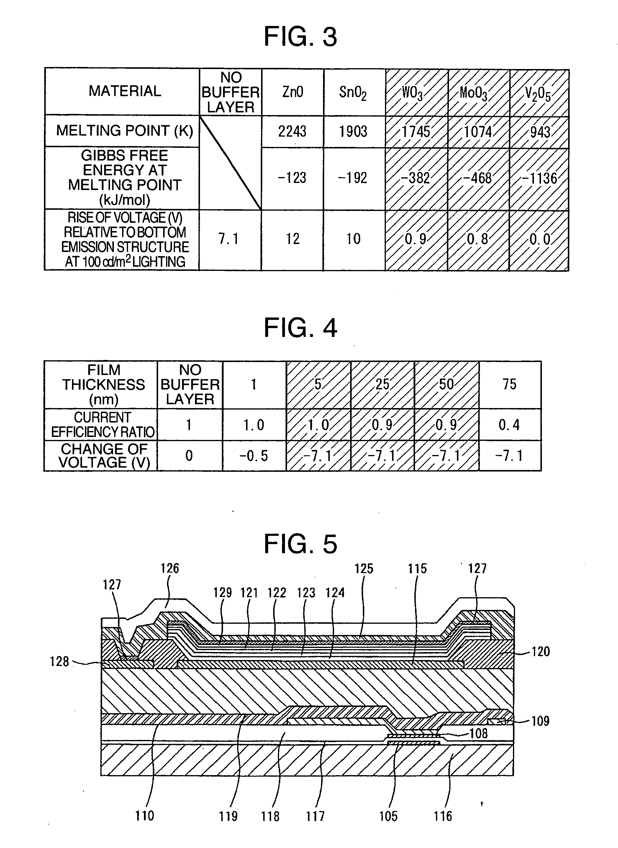
[0040] By using for the buffer layer a material which is lower in Gibbs free energy generated at the melting point than the base material of the upper electrode, it is possible to lessen the amount of oxygen radicals produced by decomposition before and in the initial phase of film forming, and to thereby suppress oxidation of the organic film.
[0058] Combination of the transparent electrode mainly composed of highly conductive indium oxide and the said buffer layer enables emission of light at a low voltage.
[0075] In the present invention, a protective layer may be formed on the upper electrode to prevent H2O and O2 in the atmosphere from penetrating into the upper electrode or the underlying organic layer.

Problems solved by technology

In the said top emission type organic light-emitting element, the layer interposed between the upper electrode and the organic film needs to be reduced in thickness because of the problem of low transmittance or low conductivity, and it is impossible to prevent the organic film from being oxidized when the upper electrode is formed, giving rise to the problem of elevated light emission voltage.
According to Patent Literature 1 mentioned above, although it is possible to protect the organic buffer layer from being damaged during high energy deposition, the buffer layer itself is oxidized when the upper electrode is formed, and the rise of light emission voltage is unavoidable.

Method used


Image

  • Organic light-emitting display device
  • Organic light-emitting display device
  • Organic light-emitting display device

Examples


example 1

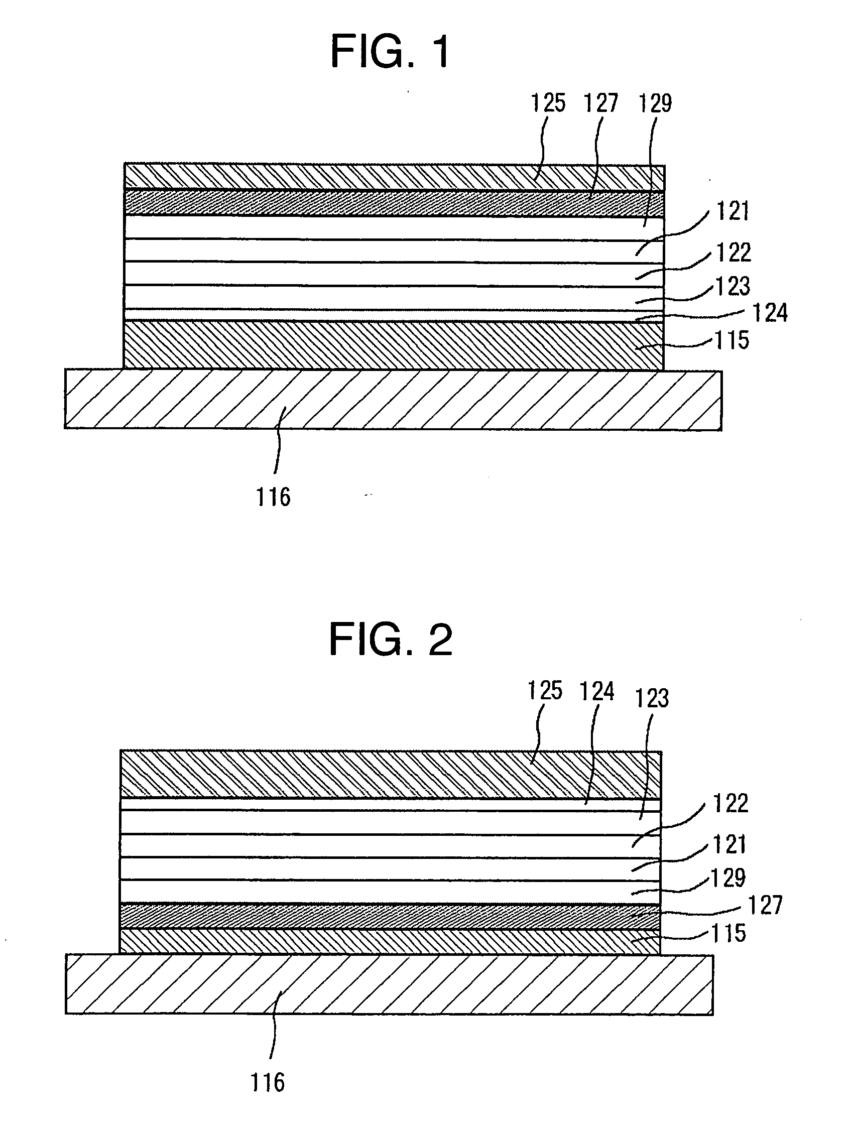
[0087] An example of organic light-emitting display device according to the present invention is explained below. FIG. 1 is a sectional view of the organic light-emitting display device according to Example 1 of the present invention. The lower electrode 115 comprises an Al film formed by EB deposition. The electrode film was patterned by using a shadow mask, and its thickness was 100 nm.

[0088] On the lower electrode 115 was formed a 0.5 nm thick LiF film as an electron injection layer 124 by vacuum deposition using a shadow mask for patterning.

[0089] On the electron injection layer 124, a film of tris(8-quinolinol) aluminum (hereinafter abbreviated as Alq), 20 nm thick, was formed by vacuum deposition. This Alq film functions as an electron transport layer 123. During the formation of the electron transport layer 123, a shadow mask was used to form its pattern. On the electron transport layer 123, a 20 nm thick co-deposition film of Alq and quinacridone (hereinafter abbreviated a...

example 2

[0096] Another example of organic light-emitting display device of the present invention is explained below. An organic light-emitting display device same as Example 1 in structure but different in thickness of the buffer layer was fabricated.

[0097] A film of vanadium oxide was formed as buffer layer 127 by EB deposition using a shadow mask for patterning. The film thickness was 1, 5, 25, 50 and 75 nm. A similar display device having no buffer layer was also made by way of comparison. The vanadium oxide film had a composition of V:O=1:2.45.

[0098]FIG. 4 shows the change of voltage and current efficiency ratio according to the buffer layer thickness at 100 cd / m2 light emission. The change of voltage shown here is the one relative to the device having no buffer layer. Current efficiency ratio is the ratio to the current efficiency of the device having no buffer layer which is supposed to be 1.

[0099] If the buffer layer thickness is less than 5 nm, oxidation of the organic film can n...

example 3

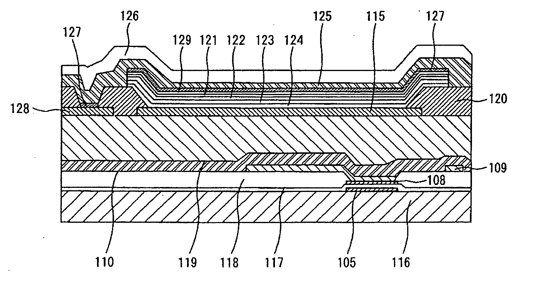
[0100] Still another example of the organic light-emitting display device according to the present invention will be explained. FIG. 5 is a sectional view of the organic light-emitting display device in the instant example of the present invention.

[0101] The organic light-emitting display device of this example is an active matrix type organic light-emitting display device comprising: a plurality of pixels; and a thin film transistor driving these pixels; wherein each of said pixels has an organic light-emitting element which comprises: an organic light-emitting layer; and an upper electrode and a lower electrode sandwiching the said organic light-emitting layer; wherein a light emitted from the organic light-emitting layer is taken out from the upper electrode side, said upper electrode is connected to an auxiliary electrode made of a low-resistance material, said organic light-emitting element has its constituent layers arranged in the order of lower electrode, organic light-emit...


PUM


Abstract

The present invention provides a top emission type organic light-emitting display device in a production of which it is possible to prevent the organic film from being oxidized when the upper transparent electrode is formed, and which is capable of emitting light at a low voltage. This organic light-emitting display device contains an organic light-emitting layer and an upper electrode and a lower electrode sandwiching the organic light-emitting layer, and is of a structure in which the emitted light is taken out from the upper electrode side, and a buffer layer mainly made of an oxide producing less oxygen by decomposition in the film-forming process than the upper electrode material is provided between the organic light-emitting layer and the upper electrode.

Description

FIELD OF THE INVENTION [0001] The present invention relates to an organic light-emitting display device. [0002] Recently, an attention has been focused on organic light-emitting display devices as next generation flat panel displays. Such organic light-emitting display devices have outstanding advantageous properties such as spontaneous light emission, wide viewing angle, and high response speed. [0003] The conventional organic light-emitting elements are of a structure comprising, laminated on a glass substrate, a first electrode made of ITO or the like, organic layers comprising a hole transport layer, a light-emitting layer and an electron transport layer, and an upper electrode of a low work function. The emitted light passes through the first electrode which is transparent, and is taken out from a back side of a substrate side of the structure. [0004] However, in the organic light-emitting display devices of the structure in which the emitted light is taken out from the back si...

Claims


Application Information

Patent Timeline
Patent Type & Authority Applications(United States)
IPC IPC(8): H01L29/06H05B33/12H05B33/14H05B33/20H05B33/22H05B33/26H05B44/00H10K99/00
CPCH01L27/3244H01L51/006H01L51/0078H01L2251/5315H01L51/5088H01L51/5092H01L51/0081H10K59/12H10K85/633H10K85/311H10K85/324H10K50/171H10K50/17H10K2102/3026B42D15/0053B42F7/025
Inventor MURAKAMI, HAJIMESHIMIZU, MASAOARATANI, SUKEKAZUNISHIMURA, ETSUKOTANAKA, MASAHIRO
Owner SAMSUNG DISPLAY CO LTD
Learn More