
Process for producing alumina coating composed mainly of alpha-type crystal structure, alumina coating composed mainly of alpha-type crystal structure, laminate coating including the alumina coating, member clad with the alumina coating or laminate coating, process for producing the member, and physical evaporation apparatu

a technology of alumina coating and crystal structure, which is applied in the direction of superimposed coating process, solid-state diffusion coating, natural mineral layered products, etc., can solve the problems of reducing the adequacy of wear-resistant base materials, cracking or peeling of coatings, and loss of applicable base materials, etc., to achieve enhanced cutting tools, high heat resistance, and high wear resistance

Inactive Publication Date: 2005-12-15
KOBE STEEL LTD
View PDF28 Cites 83 Cited by
  • Summary
  • Abstract
  • Description
  • Claims
  • Application Information

AI Technical Summary

Benefits of technology

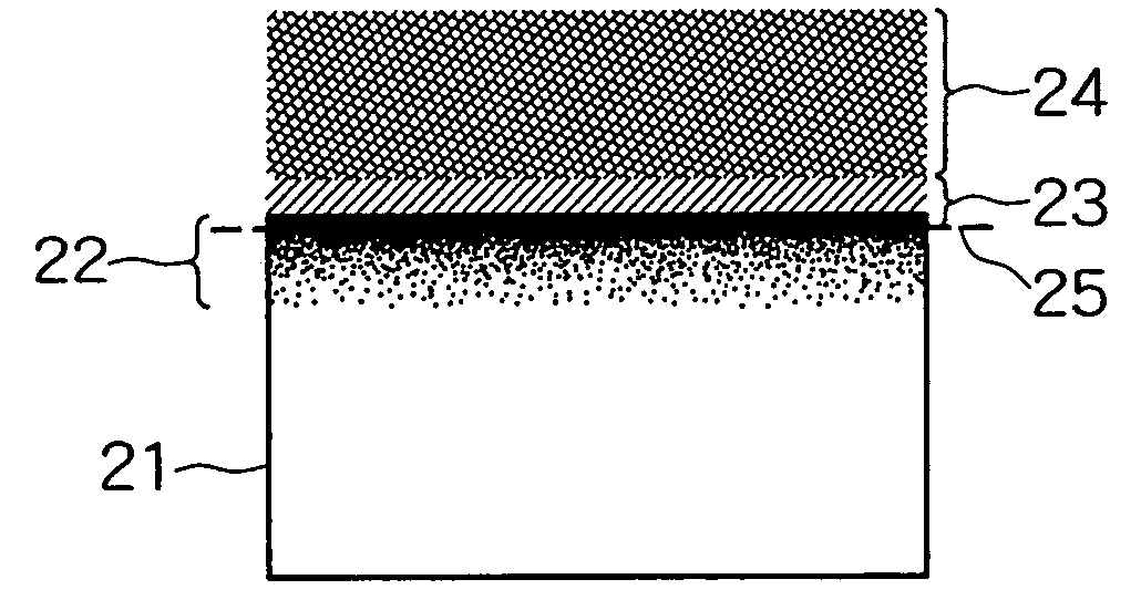
[0044] Further, it is desirable to form a composition gradient layer of both material constituting elements to be connected to the connecting interface between the hard coating and the base material or between the hard coatings, since the adhesion between the base material and the hard coating or between the hard coatings can be enhanced.
[0101] As the plasma source, a thermal electron emitting filament arranged within the vacuum chamber so that the longitudinal direction adjacent to the base material holder (planetary rotary jig) is opposed thereto may be used. According to this structure, a physical vapor deposition apparatus having a further compact device structure can be provided. The thermal electrons emitted from the filament can be efficiently guided to the base material.

Problems solved by technology

When the temperature of the cutting edge remarkably fluctuates in a wide range extending from ordinary temperature to 1000° C. or higher, the crystal structure of alumina is changed, causing a problem such as cracking or peeling of the coating.
However, since heating of the base material to 1000° C. or higher is required to form the alumina of α-type crystal structure as described above, applicable base materials are limited.
This is because a certain type of base materials might get soft, when exposed to a high temperature of 1000° C. or higher, and lose the adequacy as the base material for wear resistant member.
Even a high-temperature base material such as cemented carbide causes a problem such as deformation, when exposed to such a high temperature.
However, in case of a work material composed mainly of iron, since Cr present on the surface of the mixed crystal coating is apt to react with the iron in the work material at the time of cutting, the coating is severely worn to shorten the life.
Since a Cr-containing coating such as Cr2O3 or (CrN+Cr2O3) formed as the intermediate layer is not generally used as the material for cutting tool, the deterioration of cutting performance is feared.
Further, although crystalline α-alumina can be formed at a relatively low base material temperature according to the above-mentioned conventional method, this method has a disadvantage that a high-temperature or long-time oxidation treatment is required in the oxidation process because the intermediate layer is a stable nitride represented by CrN, in addition to the disadvantage that the intermediate layer must be limited to a nitride coating which can form, when oxidized, an oxide of corundum structure having a specified lattice constant.
Therefore, these techniques cannot sufficiently respond to the recent cutting works which are increasingly speeded up.
However, the composition of the binder phase in the sintered cBN forming the coating is limited in this technique.
Further, although the CVD method is shown as a method for forming the a -alumina coating in this technique, a high-temperature atmosphere where the substrate temperature exceeds 1000° C. is required for the formation of the coating in this method, and such a high temperature might cause the overheating and transformation of the sintered cBN of the base material to an hBN phase, which consequently leads to an undesirable situation.

Method used


Image

  • Process for producing alumina coating composed mainly of alpha-type crystal structure, alumina coating composed mainly of alpha-type crystal structure, laminate coating including the alumina coating, member clad with the alumina coating or laminate coating, process for producing the member, and physical evaporation apparatu
  • Process for producing alumina coating composed mainly of alpha-type crystal structure, alumina coating composed mainly of alpha-type crystal structure, laminate coating including the alumina coating, member clad with the alumina coating or laminate coating, process for producing the member, and physical evaporation apparatu
  • Process for producing alumina coating composed mainly of alpha-type crystal structure, alumina coating composed mainly of alpha-type crystal structure, laminate coating including the alumina coating, member clad with the alumina coating or laminate coating, process for producing the member, and physical evaporation apparatu

Examples


working examples

[0406] The present invention will be described further concretely according to working examples. The present invention is never limited by the following examples, and modification and variation of the present invention are possible within the range adaptable to the gist of the previous and following descriptions, and naturally included in the technical scope of the present invention.

(1) Working Example for Fist Mode

Example 1

[0407] A working example for the first means (Mode 1-a and b) will be described. A cemented carbide base material of 12.7 mm×12.7 mm×5 mm, which was mirror-polished (Ra=about 0.02 □m) and ultrasonically cleaned in an alkali bath and a pure water bath followed by drying, was used for cladding of a laminate coating.

[0408] In this example, formation of a hard coating, oxidation treatment of the hard coating, and formation of an α-type-based alumina coating were carried out by use of a vacuum deposition apparatus shown in FIG. 4 (manufactured by Kobe Steel, Ltd. ...

example 1

[0468] By use of base materials of a-c, the metal ion bombardment treatment, the oxidation treatment and the formation of alumina coating were successively carried out in a vacuum deposition apparatus (manufactured by Kobe Steels, Ltd. composite machine AIP-S40) shown in FIG. 7.

[0469]

[0470] a. Cemented carbide base material (12 mm×12 mm×5 mm)

[0471] b. Si wafer (silicone wafer) (20 mm×20 mm)

[0472] c. Cemented carbide base material (12 mm×12 mm×5 mm) with

[0473] TiAlN coating with a thickness of about 2 nm formed thereon by AIP

[0474] The metal ion bombardment treatment was carried out as follows.

[0475] A sample (base material) 2 was set in a base material holder (planetary rotary jig) 4 on a rotary table 3 within a chamber 1. After the chamber 1 was evacuated to a vacuum state, the sample was heated to 600° C. by heaters 5 set in two positions of side surfaces and in the center part within the chamber 1, and retained at this temperature for 30 minutes.

[0476] Thereafter, the powe...

example 2

[0480] The metal ion bombardment treatment, the oxidation treatment and the formation of alumina coating were carried out in the same manner as in Example 1 except introducing, at the metal ion bombardment treatment, nitrogen into the chamber 1 so as to have a partial pressure of 0.05 Pa to perform the metal ion bombardment treatment under a nitrogen atmosphere (Nos. 4-6 of Table 5).


PUM

PropertyMeasurementUnit
Temperatureaaaaaaaaaa
Fractionaaaaaaaaaa
Thicknessaaaaaaaaaa

Abstract

A process for producing an alumina coating composed mainly of a-type crystal structure especially excelling in heat resistance, comprising (1) providing a laminate coating including a hard coating composed of a metal component containing Al and Ti as unavoidable elements and a compound of B, C, N, O, etc., oxidizing the hard coating to thereby form an oxide-containing layer, and forming an alumina coating composed mainly of a-type crystal structure on the oxide-containing layer. Alternatively, the process comprises (2) forming a hard coating composed of a metal whose standard free energy for oxide formation is greater than that of aluminum and a compound of B, C, N, O, etc., oxidizing the surface of the hard coating to thereby form an oxide-containing layer, and forming an alumina coating while being accompanied by reduction of the oxide at the surface of the oxide-containing layer.

Description

TECHNICAL FIELD [0001] The present invention relates to a process for producing an alumina coating composed mainly of α-type crystal structure, the alumina coating composed mainly of α-type crystal structure, a laminate coating including the alumina coating, a member clad with the alumina coating or the laminate coating, a process for producing the member, and a physical vapor deposition apparatus used for production thereof. [0002] More specifically, the present invention relates to an effective process capable of forming an alumina coating composed mainly of α-type crystal structure excellent in wear resistance and heat resistance to be applied onto a wear resistant member such as a cutting tool, sliding member, or metal mold, in a low-temperature condition which never impairs the characteristic of the base material of the cutting tool, sliding member or the like, the resulting alumina coating composed mainly of α-type crystal structure, a laminate coating including the alumina co...

Claims


Application Information

Patent Timeline
IPC IPC(8): C23C8/02C23C8/10C23C28/00C23C30/00
CPCC23C8/02C23C8/10C23C14/081C23C30/005C23C28/321C23C28/36C23C28/34C23C28/341C23C28/345C23C28/3455C23C28/347C23C28/322
Inventor KOHARA, TOSHIMITSUIKARI, YOSHIMITSUTAMAGAKI, HIROSHI
Owner KOBE STEEL LTD
Learn More