Solar, catalytic, hydrogen generation apparatus and method

a hydrogen generation and catalytic technology, applied in the field of solar energy collection and storage, can solve the problems of frictional losses through the turbine, inefficiency in each aspect of the generation, delivery and utilization of electrical energy, and process may not be particularly efficient thermodynamically or environmentally, etc., to achieve high thermodynamic availability, high temperature, and efficiency loss

Inactive Publication Date: 2006-03-09
PURESCI
View PDF23 Cites 130 Cited by
  • Summary
  • Abstract
  • Description
  • Claims
  • Application Information

AI Technical Summary

Benefits of technology

[0020] Accordingly, if nitrogen is used as a sweep gas, hydrogen can be immediately reacted on the sweep side of the barrier wall to produce anhydrous ammonia which subsequently may be cooled to liquid phase. Since the density of liquid ammonia is 1325 grams per liter, and contains about 17.6 percent hydrogen, this provides 233 grams of hydrogen per liter of storage, a density greater than liquid hydrogen. Effectively, a liter of ammonia could contain approximately 7.8 kilowatt hours of energy in hydrogen to be cracked from the ammonia for use. Meanwhile, anhydrous ammonia can be handled by conventional technologies that do not require excessive pressures, temperatures, or esoteric and expensive metals.
[0021] A hydrogen generator in accordance with the invention was developed to take advantage of heat from many sources, including solar and other alternative energy sources. For example, thermal effluents from industrial processes, and the like may provide energy to be recovered. Solar energy has the advantage that it provides a high thermodynamic availability, which can be translated into very high temperatures. Nevertheless, an appara

Problems solved by technology

These are complicated by the precautions necessary to handle the products due to their extreme reactivity.
Depending upon the source of electrical energy, this process may not be particularly efficient thermodynamically or environmentally.
For instance, if the electrical energy is derived from a standard fossil fuel fired generation plant, much inefficiency is involved in each aspect of the generation, delivery, and utilization of the electrical energy.
There are frictional losses through the turbine.
The turbine drives a generator, which also has frictional losses as well as eddy current and resistance losses.
The generated electricity is delivered as alternating current over transmission lines that have line losses, after which the alternating curre

Method used


Image

  • Solar, catalytic, hydrogen generation apparatus and method
  • Solar, catalytic, hydrogen generation apparatus and method
  • Solar, catalytic, hydrogen generation apparatus and method

Examples


Embodiment Construction

[0052] It will be readily understood that the components of the present invention, as generally described and illustrated in the Figures herein, could be arranged and designed in a wide variety of different configurations. Thus, the following more detailed description of the embodiments of the system and method of the present invention, as represented in FIGS. 1 through 23, is not intended to limit the scope of the invention, as claimed, but is merely representative of the presently preferred embodiments of the invention.

[0053] The presently preferred embodiments of the invention will be best understood by reference to the drawings, wherein like parts are designated by like numerals throughout.

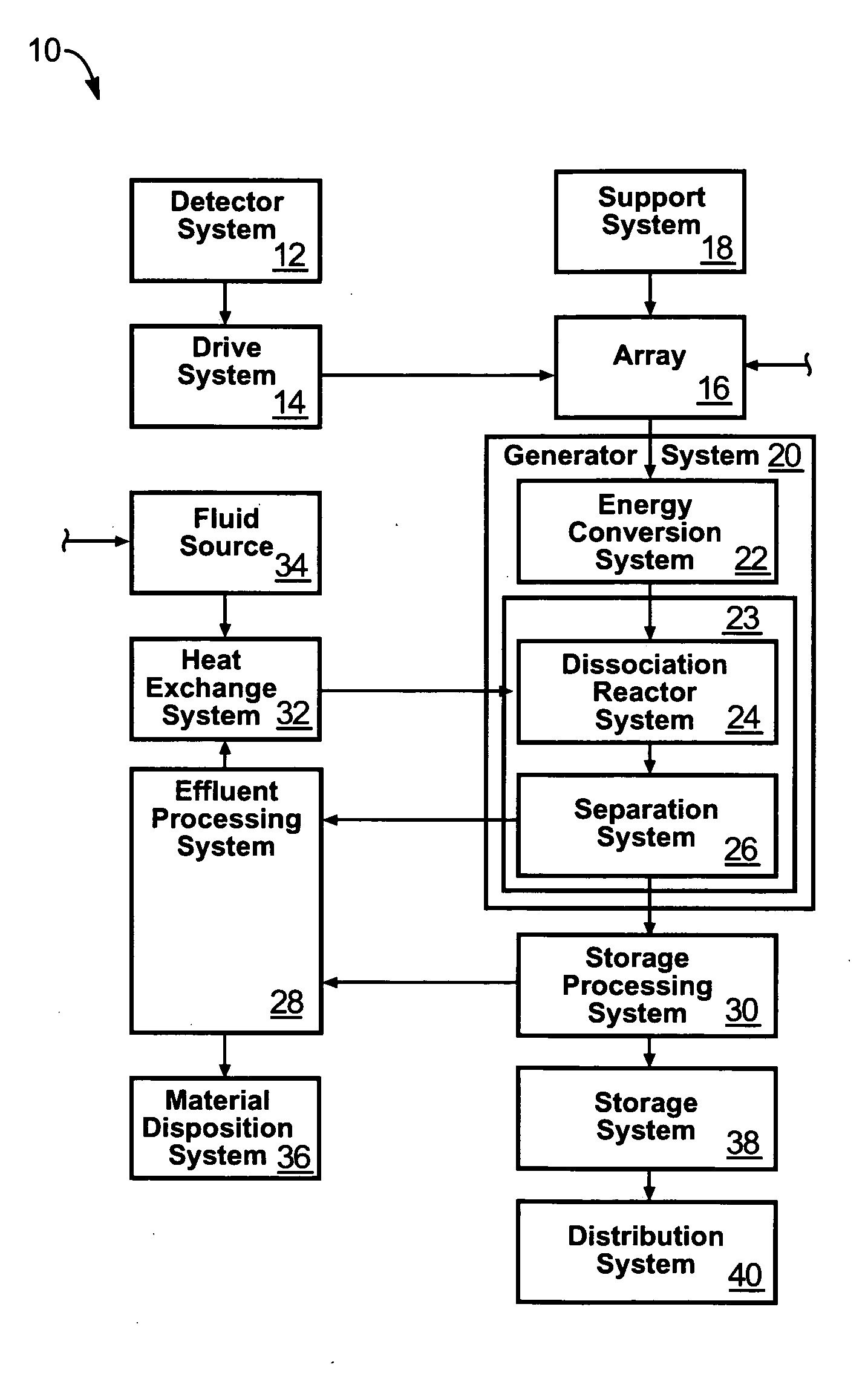
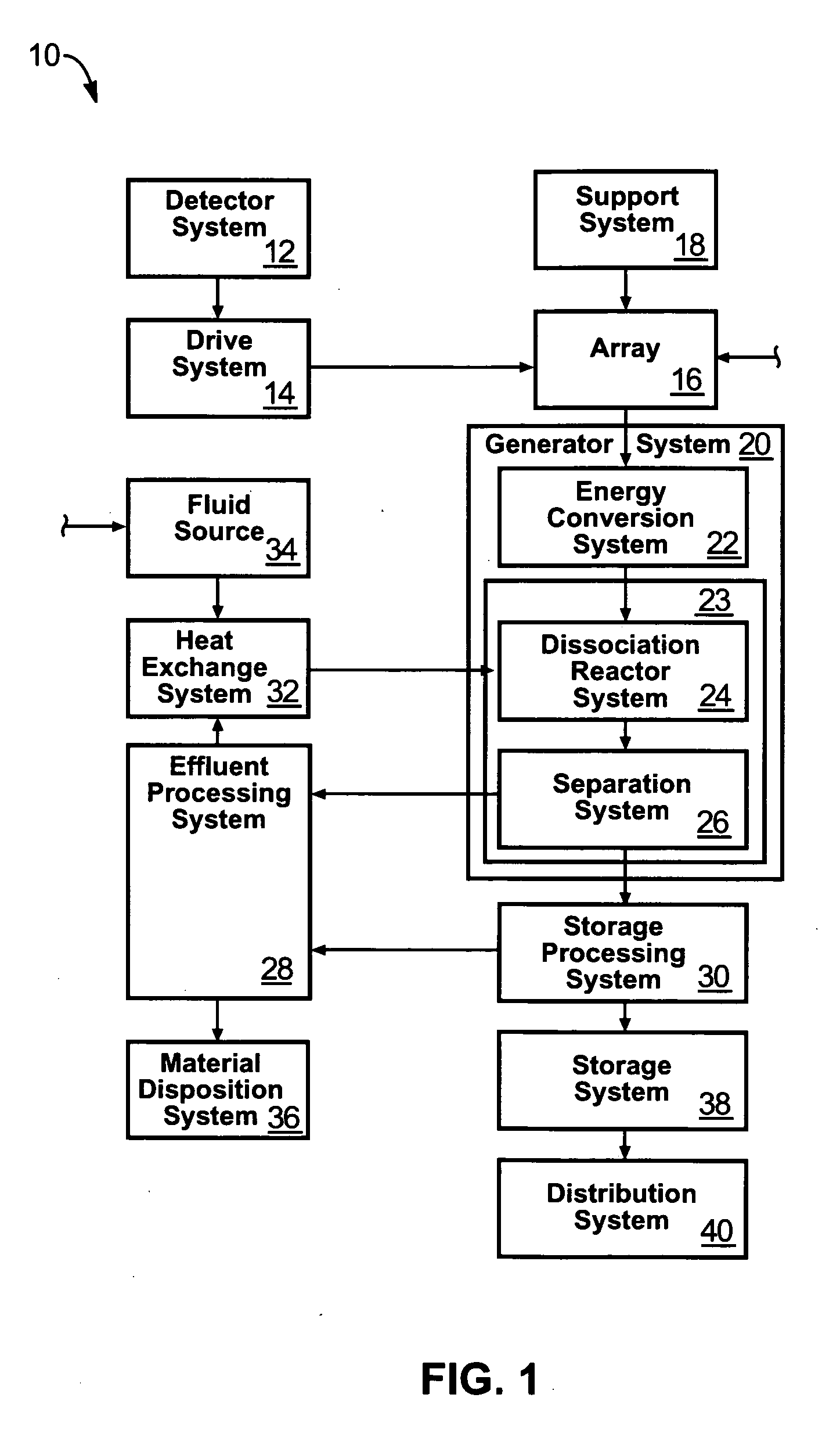
[0054] Referring to FIG. 1, an apparatus, method, and system 10 in accordance with the invention may include a detector system 12 for detecting radiation from the sun, in order to track the sun. A drive system 14 may provide mechanisms to move an array 16, such as an array 16 of mirrors coll...


PUM


Abstract

An apparatus for producing hydrogen may include a collector of radiation to concentrate solar radiation on a converter having an absorptivity to convert the solar radiation to thermal energy to drive a chemical process using a feedstock to dissociate into an output chemical and a byproduct. A separator separates the output and byproduct, after which a reactor reacts the output to form a storage chemical, reactive to produce energy but sufficiently stable for safe handling outside designation as an energetic material. The separator may have a porosity to substantially pass hydrogen and block oxygen and water. A sweep gas may sweep hydrogen away from the separation barrier to change equilibrium. Catalysts may reduce temperature of dissociation and a subsequent reaction to combine it in a more stable, storable form.

Description

BACKGROUND [0001] 1. The Field of the Invention [0002] This invention relates to solar energy collection and storage and, more particularly, to novel systems and methods for solar generation and storage of chemical energy. [0003] 2. Technical Background of the Art [0004] Water can be, and has been, dissociated into hydrogen and oxygen by several methods. Each method has its advantages and disadvantages. These are complicated by the precautions necessary to handle the products due to their extreme reactivity. [0005] Among the methods of water dissociation are electrolysis and thermal dissociation. Electrolysis occurs when a direct current is applied to two electrodes that are placed in a water bath. Hydrogen is produced at the cathode (negatively charged electrode) and oxygen is produced at the anode (positively charged electrode.) The advantage to this system is that the oxygen and hydrogen are separated as they are produced. Therefore, no explosive solution of the products is forme...

Claims


Application Information

Patent Timeline
IPC IPC(8): H01L35/00
CPCC01B3/042C01B3/503C01B3/505C01B2203/0405C01B2203/041Y02E60/364F24J2/07F24J2/38F24J2/40F24J2/54Y02E10/41C01B2203/0465F24S50/20F24S20/20F24S30/40F24S50/00Y02E10/40Y02E60/36Y02P20/133
Inventor RUCKMAN, JACK HUGHSCHURIG, ALMA K.ANDERSON, KEITH
Owner PURESCI
Why Eureka
Try Eureka