Electron source

a technology of electron source and source material, applied in the field of electron source, can solve the problems of poor reproducibility, short stable operation, and inapplicability to industrial applications

Active Publication Date: 2006-04-13
DENKA CO LTD
View PDF5 Cites 10 Cited by
  • Summary
  • Abstract
  • Description
  • Claims
  • Application Information

AI Technical Summary

Benefits of technology

[0012] Under the above circumstances, the present inventors have conducted various studies and as a result, have found a supply source which is suitable for ...

Problems solved by technology

However, on the other hand, it is stated that the time for stable operation is very short at a level of a few hours, and it will be required to carry out thermal treatment at a temperature of at least 1,500 K repeatedly, which is considered to be not practically useful for industrial application.
Further, a case wherein barium oxide is used as a supply source, has also been reported, but in such a case, it is pointed out that the electron emission will be of four fold sym...

Method used


Image

  • Electron source
  • Electron source
  • Electron source

Examples


examples

[0051] Now, the present invention will be described in further detail with reference to Examples. However, it should be understood that the present invention is by no means restricted to such Examples.

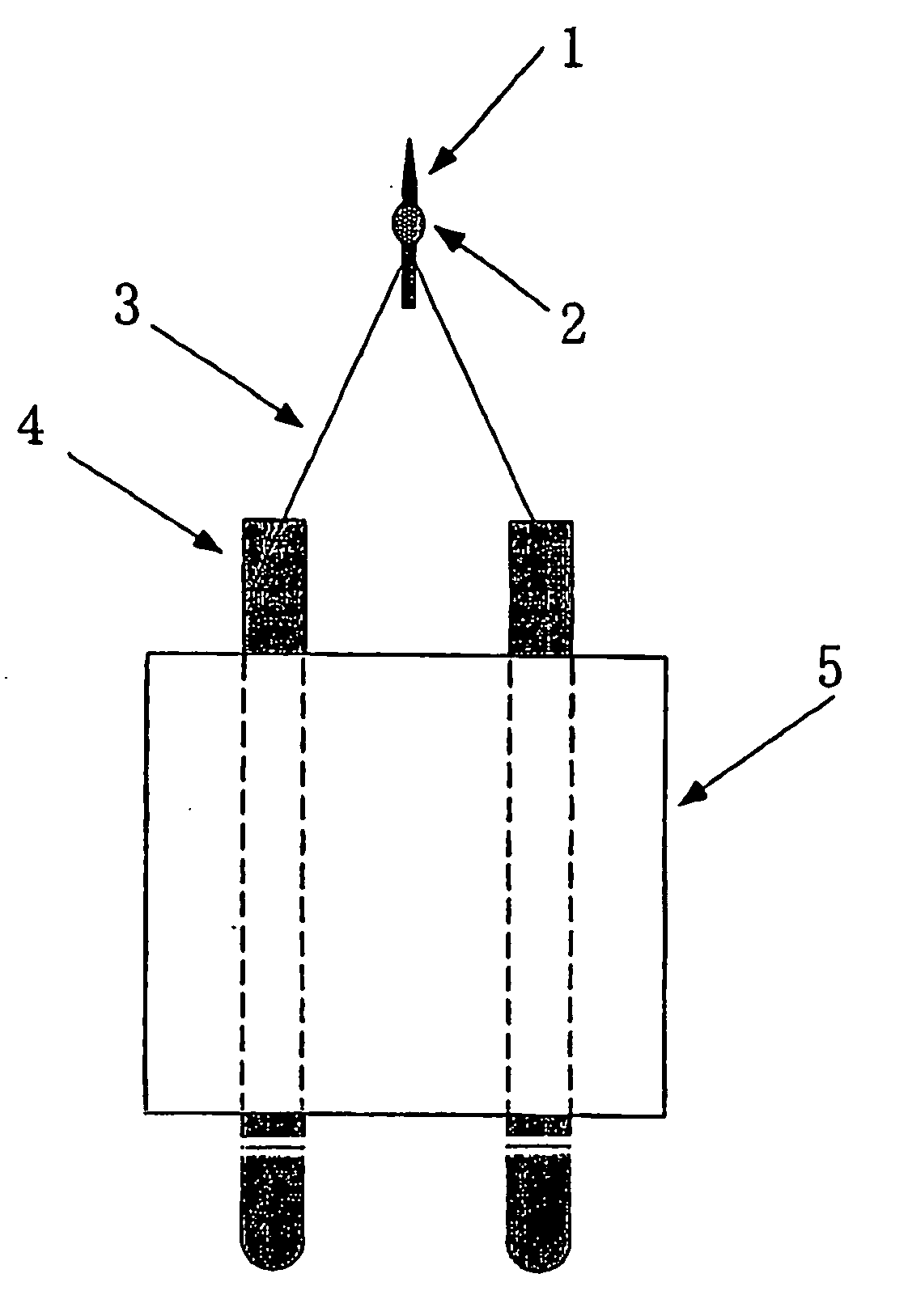
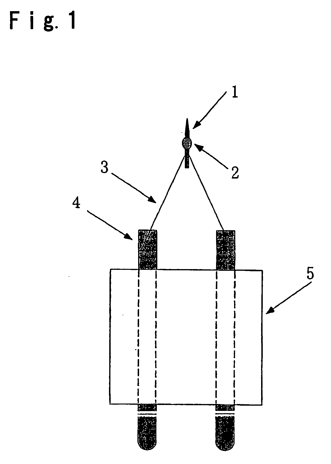
[0052] A tungsten filament was fixed by spot welding to conductive terminals brazed to electric glass, and then, a needle obtained by cutting a single crystal tungsten thin wire having orientation, was attached by spot welding to the above filament and further electropolished so that the curvature radius of the apex of the needle would be about 1 μm, to obtain an intermediate of electron source.

[0053] Further, as a material constituting the supply source, comparison was made by using each of a commercially available barium aluminate (BaAl2O4) powder, a barium oxide powder, a mixture of barium oxide, calcium oxide and aluminum oxide powders (molar ratio of 5:3:2), and a mixture of barium oxide, strontium oxide and calcium oxide powders (molar ratio of 5:4:1). Using isoamyl acetate as...

examples 1 to 4

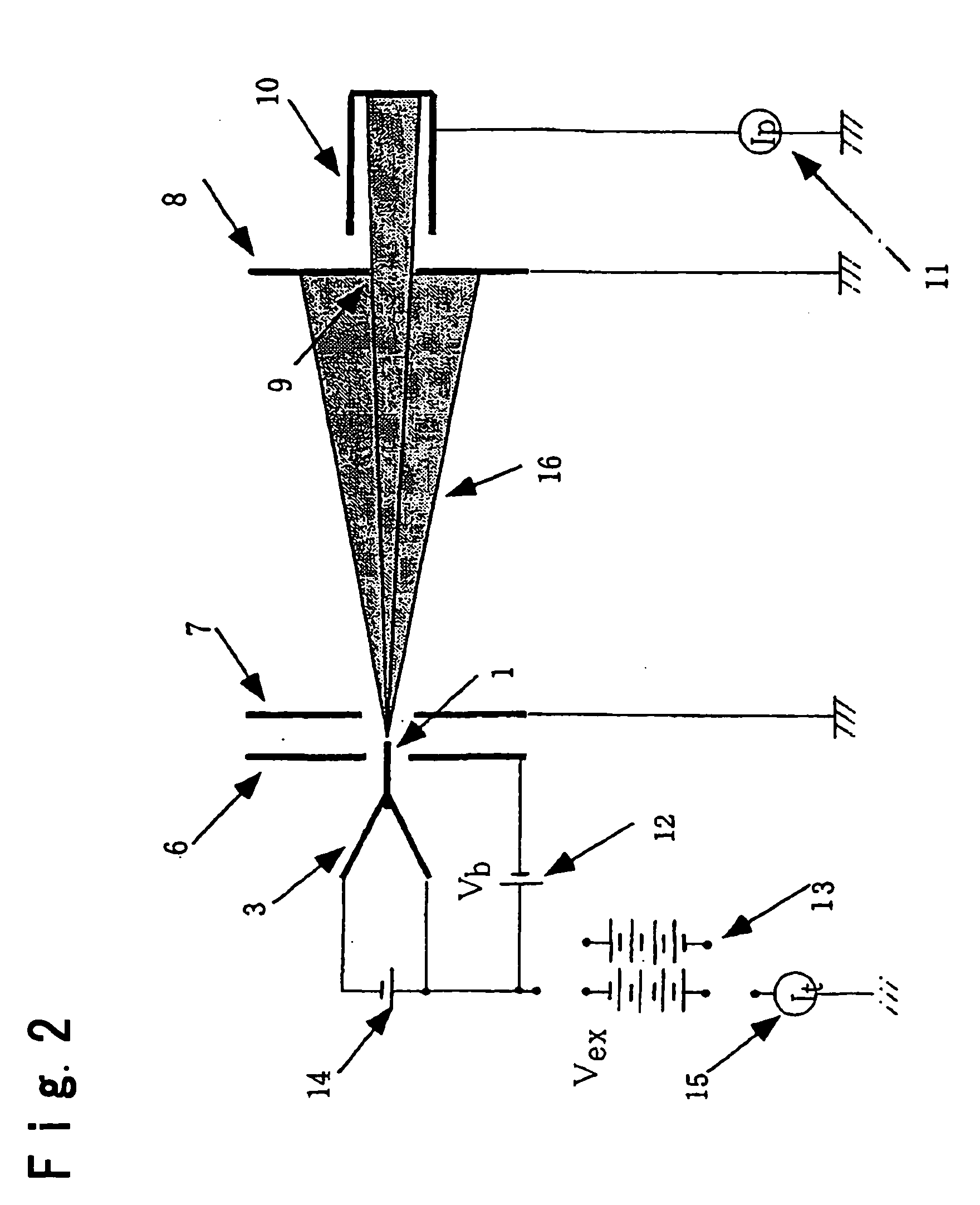
[0057] An electron source having barium aluminate as a supply source, is introduced into a vacuum chamber, and the chamber is evacuated to an ultrahigh vacuum of 3×10⁻¹⁰ Torr (4×10⁻⁸ Pa), whereupon an electric current is conducted to the filament 3 to heat the needle 1 at 1,500 K thereby to turn on the supply source.

[0058] Thereafter, two types i.e. ones following procedure 1 and procedure 2 (Examples 1 and 2) and ones following procedure 1′ and procedure 2 (Examples 3 and 4), were compared.

[0059] Procedure 1: While the needle was maintained at from 1,000 to 1,600 K and the bias voltage of the suppresser was Vb=0 V, a positive high voltage was applied to the needle and maintained for a few tens hours.

[0060] Procedure 1′: While the needle was maintained at from 1,000 to 1,600 K, a bias voltage of a few hundreds V was applied to the suppresser, and a negative high voltage was applied to the needle and maintained for a few tens hours.

[0061] Procedure 2: The needle was set at an ope...


PUM


Abstract

To provide an electron source to be used for a surface analyzer such as a scanning or transmission electron microscope or an Auger electron spectroscope, or an electron beam lithography machine, particularly for a semiconductor wafer inspection apparatus such as a scanning electron microscope to be used at a low acceleration with an electron beam acceleration voltage of up to 1 kV, CD SEM or DR SEM. An electron source wherein a barium supplying source consisting of a complex oxide comprising barium oxide and an oxide of metal other than barium, is provided at a portion of a single crystal needle of tungsten or molybdenum.

Description

TECHNICAL FIELD [0001] The present invention relates to an electron source for a scanning electron microscope, a transmission electron microscope, and a surface analysis apparatus such as an Auger electron spectroscope, a semiconductor wafer inspection apparatus or an electron beam lithography machine, particularly an electron source to be used for a scanning electron microscope, and a wafer inspection apparatus such as CD and DR SEM, of which electron beam is at a low accelerating voltage up to 1 kV. BACKGROUND ART [0002] In recent years, in order to obtain an electron beam having higher brightness, a Schottky electron emission source (hereinafter referred to also as an electron source) employing a needle electrode of tungsten single crystal, has been used. This electron source is one wherein a covering layer comprising zirconium and oxygen (hereinafter referred to as a ZrO covering layer) is formed on a tungsten single crystal needle having an axial orientation being <100> o...

Claims


Application Information

Patent Timeline
IPC IPC(8): H01J1/02G02B5/00G02B5/20G02F1/1335H01J1/14H01J1/15H01J1/304H01J37/06H01J37/073
CPCH01J1/14H01J1/3044H01J37/06H01J2237/06308H01J2237/06316
Inventor TERUI, YOSHINORINONOGAKI, RYOZO
Owner DENKA CO LTD
Why Eureka
Try Eureka