Cell tray

a cell tray and cell technology, applied in laboratory glassware, fluorescence/phosphorescence, optical radiation measurement, etc., can solve the problem of cell destruction by electron microscope, and achieve the effect of large-scale production

Active Publication Date: 2006-06-08
NANOPOINT
View PDF10 Cites 18 Cited by
  • Summary
  • Abstract
  • Description
  • Claims
  • Application Information

AI Technical Summary

Benefits of technology

[0012] The POINT microscope is suitable for imaging living biological samples using a technique that accommodates large-scale production. The POINT near-fi

Problems solved by technology

Currently, confocal microscopes, MRI and ultrasound cannot image to a 5

Method used


Image

  • Cell tray
  • Cell tray
  • Cell tray

Examples


Embodiment Construction

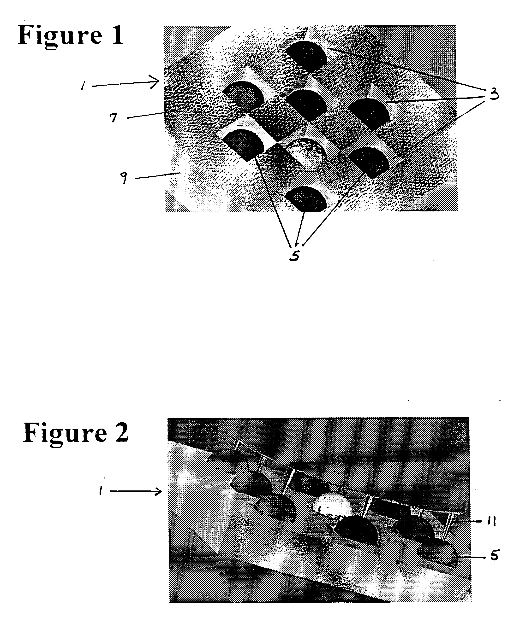
[0030] The present invention provides a method of containing an ordered array of cells 1 in precise locations for use in parallel analysis and processing of cells 5 simultaneously.

[0031] As shown in FIG. 1, each cell cubicle or silo 3, in the square cell array 1, is located equidistant from its nearest neighbors in an orthogonal direction.

[0032] The cell tray 1 is fabricated using micro-machining techniques. A layer of chrome is deposited onto the cell carrier substrate 9. A layer of photoresist 7 is spin coated over the chrome. The material for the cell carrier substrate 9 includes, but is not limited to, fused silica (quartz), soda-lime glass, silicon, germanium, sapphire, and plastic. Other base substrates are used depending on the desired optimal transmission properties in various parts of the electromagnetic spectrum.

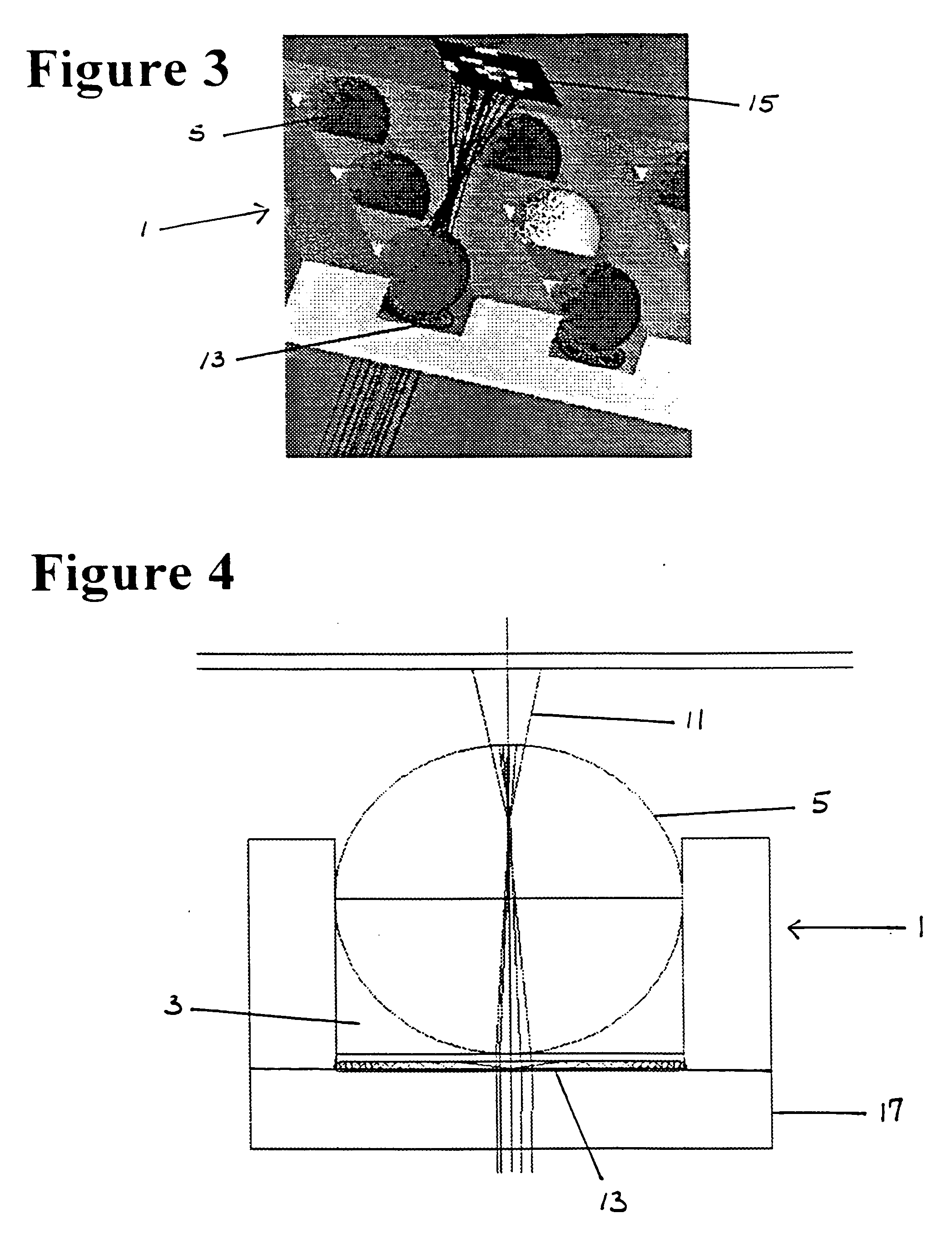
[0033] A lithographic mask is designed on computer and directly written on the photoresist with a laser scanning microscope. Alternatively a two-axis Ronchi rul...


PUM


Abstract

A cell tray has a multi-dimensional array of cells in precise, equally spaced wells (cubicles or silos) containing medium of interest. The ordered cell array enables automated processing as well as simultaneous monitoring and analyzing of a large matrix of cells, biological fluids, chemicals and/or solid samples. The invention is an integrated device and is fabricated into substrates similar to microscope slides. The ordered array of cells in precise locations helps in parallel analysis and processing of cells simultaneously. Each cell cubicle or silo in the array is located equidistant from its nearest neighbors in an orthogonal direction. The location of each well can be precisely measured and recorded in an automated processing system. Included in the bottom of each cell well is an optional micro-lens. An array of probes provides parallel cell processing and monitoring capabilities, including microinjection and microscope analysis. The cell tray when integrated with the Precision Optical Intracellular Near Field Imaging/Spectroscopy Technology (POINT or NANOPOINT) device results in sub-wavelength high-resolution imaging with a nanosensor array capable of imaging inner regions of living cells without destroying its natural environment.

Description

[0001] This application claims the benefit of U.S. Provisional Application No. 60 / 421,566, filed Oct. 28, 2002 and U.S. patent application Ser. No. 10 / 290,528 filed Nov. 8, 2002.BACKGROUND OF THE INVENTION [0002] Current methods of cell analysis involve living cells cultured in petri dishes, well plates and on microscope slides. These previous methods of culturing live cells suffer from inconsistent arrangement of cells and slow processing times. The arrangement of the cells in previous cell analysis methods is random, with areas of high cell congregation and other regions where cells are sparsely distributed. [0003] Biological research laboratories and biological instrument and supply companies are constantly looking for new methods to make cell analysis more efficient. [0004] Needs exist for improved simultaneous multiple cell analysis, observation and cell injections. SUMMARY OF THE INVENTION [0005] The present invention preferably has a two-dimensional array of cells in precise,...

Claims


Application Information

Patent Timeline
IPC IPC(8): G01N1/10
CPCB01L3/5027B01L3/5085B01L2200/0668B01L2300/0654B01L2300/0819B01L2300/0822C12M23/12C12M41/46G01N21/03G01N21/253G01N21/64G01N35/00029G01N35/028G01N2015/1486G01N2015/1493G01N2035/00158G01N2021/0346
Inventor O'CONNELL, DANIEL G.
Owner NANOPOINT
Why Eureka
Try Eureka