Charged particle beam apparatus

Inactive Publication Date: 2006-08-10
HITACHI HIGH-TECH CORP
View PDF14 Cites 30 Cited by
  • Summary
  • Abstract
  • Description
  • Claims
  • Application Information

AI Technical Summary

Benefits of technology

[0013] The above problems with prior arts can be solved by performing an aberration correction at a stage before a charged particle beam generated in the charged particle beam source is highly accelerated, i.e., at an initial stage where the energy of the charged particle beam is relatively low. An example of initial acceler

Problems solved by technology

The prior arts and inventions described in the above documents are hardly practical.
316-325) allows both of spherical aberration and chromatic aberration theoretically, but is not practical in the case of the aberration correction for electron beams with a large acceleration energy.
That is, in the Zach's method, when acceleration energy is increased, it is necessary to extend the aberration corrector in proportional to the acceleration voltage, narrow the bore radius of a quadrupole element in proportion to a square root of the acceleration voltage, or increa

Method used


Image

  • Charged particle beam apparatus
  • Charged particle beam apparatus
  • Charged particle beam apparatus

Examples


first embodiment

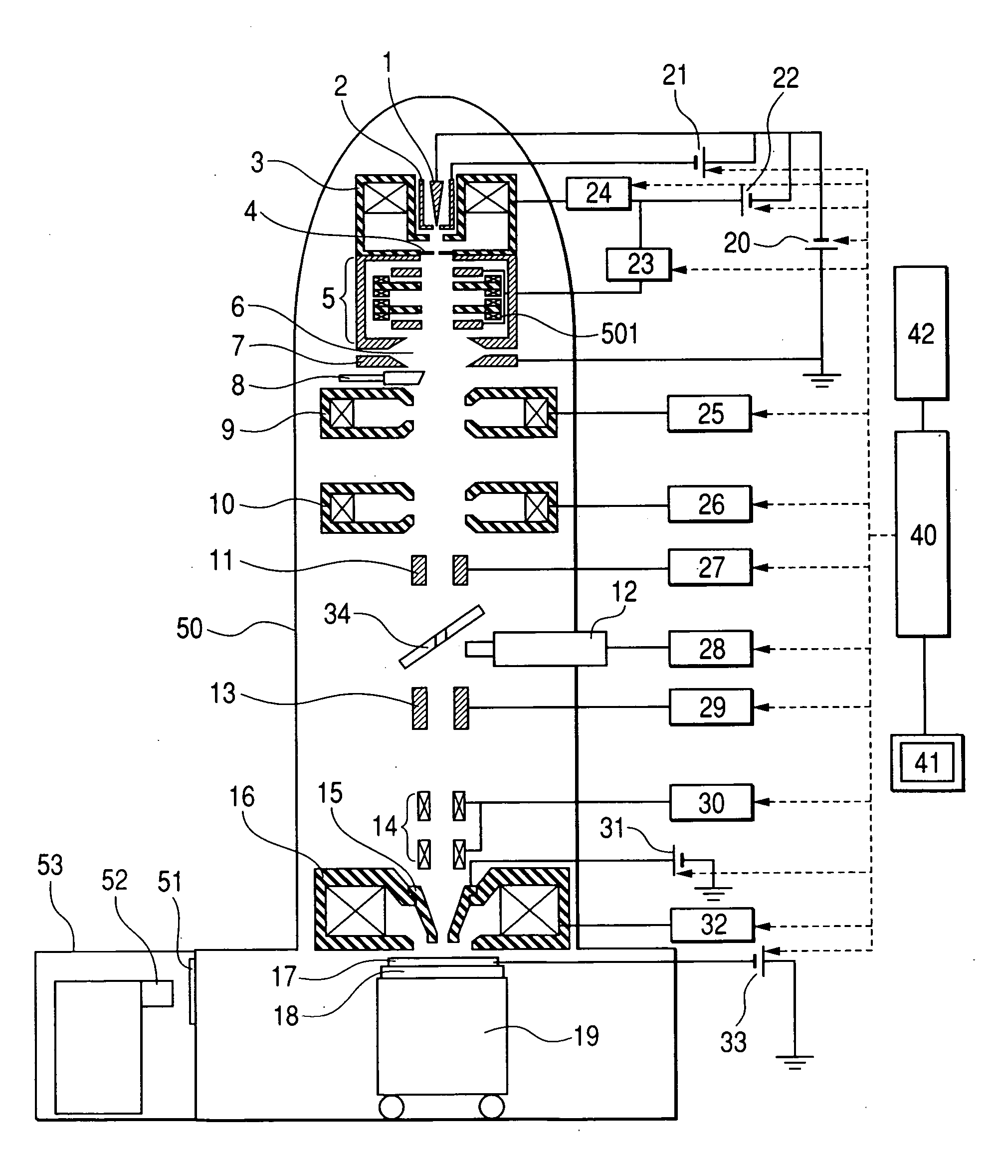
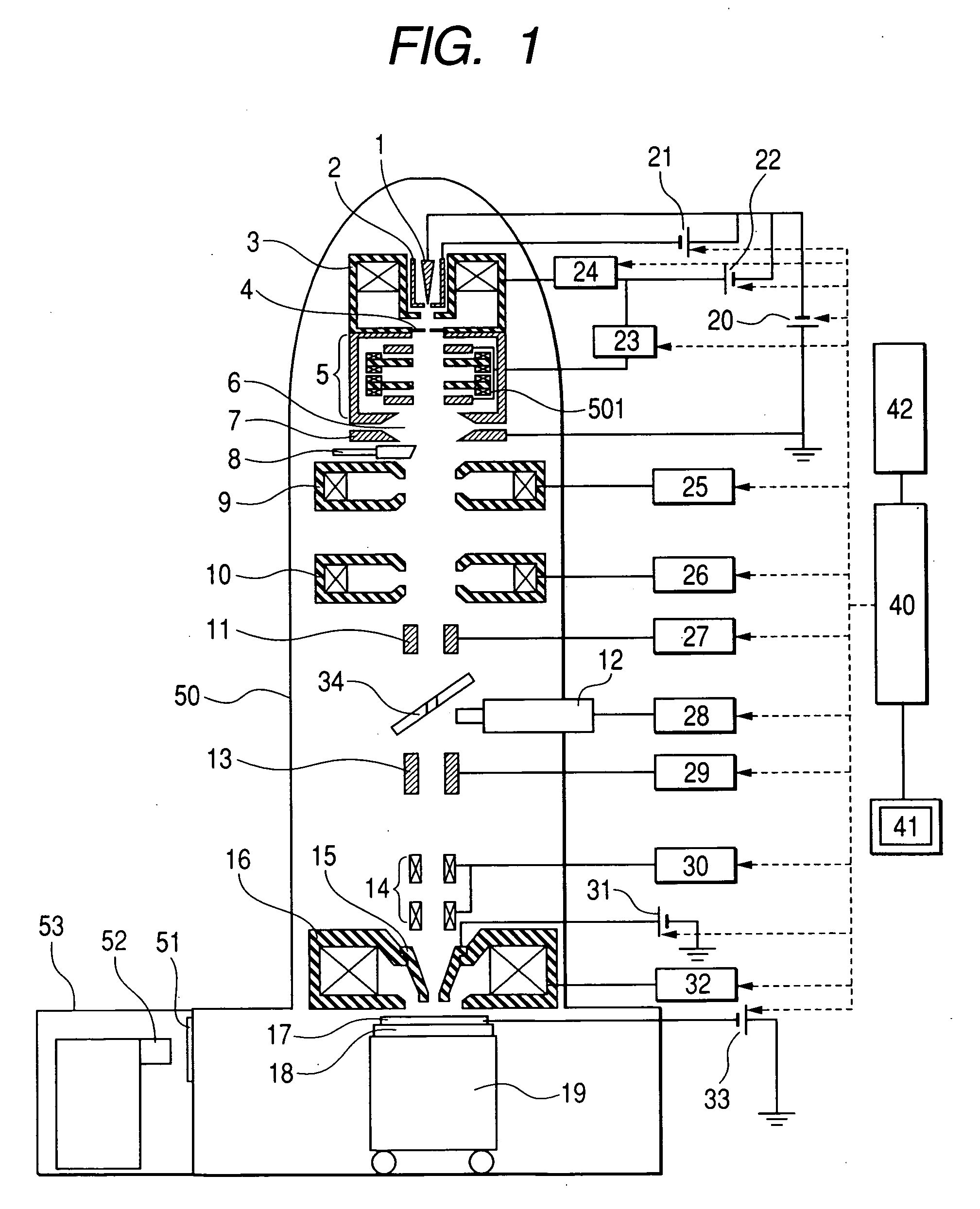
[0021] Preferred embodiments of a scanning electron microscope are described below with reference to the drawings. FIG. 1 shows an entire configuration of a scanning electron microscope. A Schottky electron source 1 is an electron source that utilizes the Schottky effect by spreading oxygen and zirconium in a single crystal of tungsten, and near the Schottky electron source is provided a suppressor electrode 2. A magnetic lens 3 is disposed in the vicinity of this electron source. The upper magnetic pole of this magnetic lens 3 doubles as an extraction electrode.

[0022] The magnetic lens 3 is unnecessary in principle, but it is better to provide this lens for adjustment of virtual source position (object point with respect to an aberration corrector 5). Without the effect of the magnetic lens 3, the virtual source position as seen from the aberration corrector 5 side of an extracted beam from the Schottky electron source 1 at extraction voltage V1 would be several centimeter above t...

second embodiment

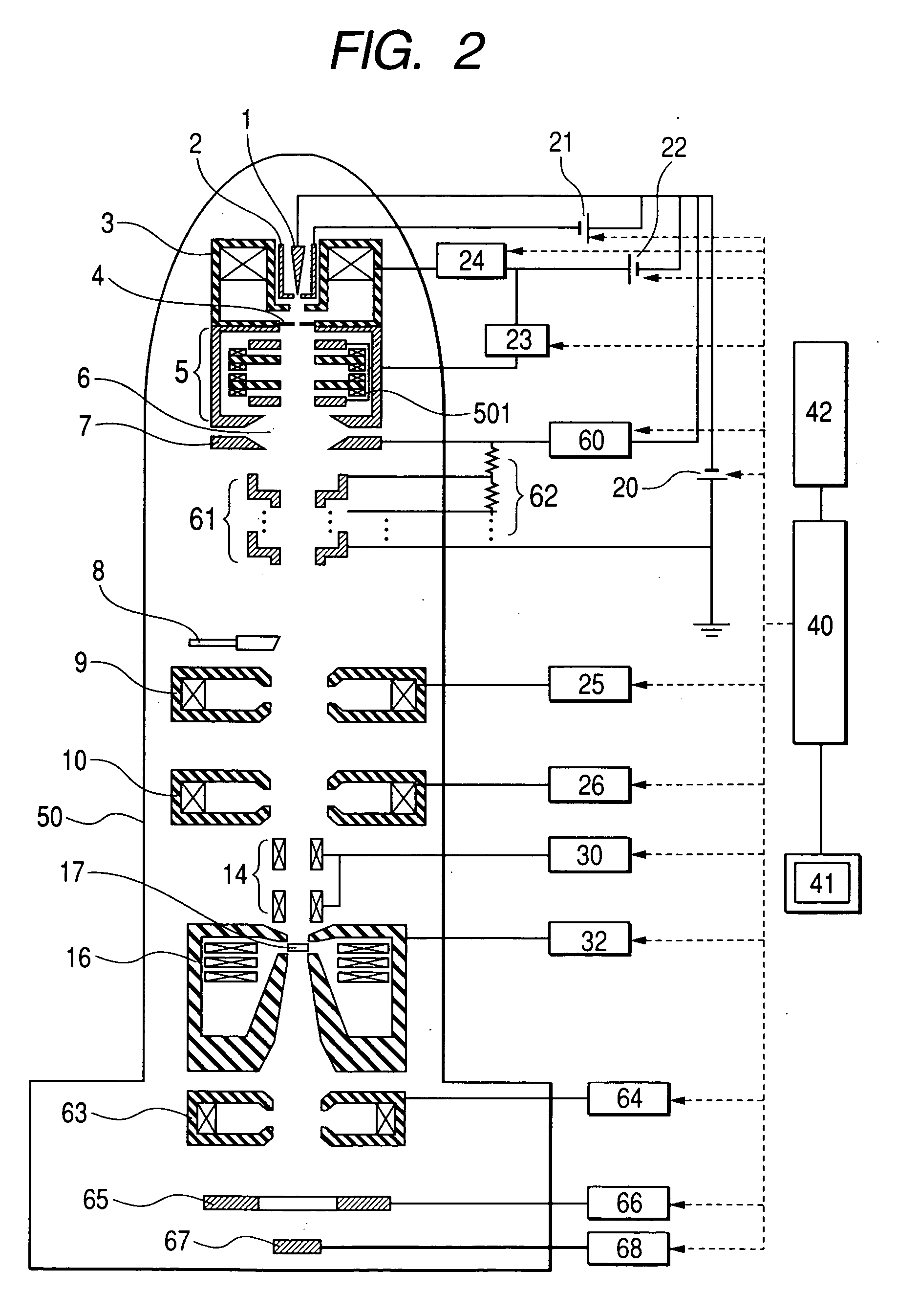
[0038]FIG. 2 shows an example application of the present invention to the scanning transmission electron microscope (STEM).

[0039] The electron gun section has the same configuration as in the first embodiment, in which an acceleration tube 61 is disposed under the Butler type electrostatic lens 6, and an electron is accelerated by a high voltage power supply 20. Under the acceleration tube 61 is provided a space called an electron gun chamber (not shown), where the electron gun section is evacuated up to ultra high vacuum by an ion pump or the like, to separate from the low vacuum side by means of the valve 8. The accelerated electron beam leaves the acceleration tube, is spread at an appropriate angle by the condenser lens 9 and 10, and then focused on the specimen 17 by the objective lens 16.

[0040] This focused beam is scanned on the specimen 17 by the scanning coil 14. The large angle spread beam of the beam that has been transmitted through the specimen and spread is detected ...

third embodiment

[0042] For Third Embodiment, an example application to the electron gun is described. FIG. 3 shows an example configuration of an electron gun of this embodiment. In the electron gun of First Embodiment, if extraction voltage V1 and acceleration voltage V1 are determined, the intensity of the Butler type electrostatic lens 6 is determined. In order to provide more likelihood to electro-optic systems, even when the extraction voltage V1 and acceleration voltage V0 are determined, it is possible to control the intensity of the electrostatic lens, by inserting an electrode 70 to which a midpoint potential is given, on the lower electrode 7 of the Butler type electrostatic lens via an insulating tube 601 to form a 3-plate electrode configuration, as shown in FIG. 3. Particularly, V0 can be used more widely on the deceleration side, making it possible to control the positions of the object point and image point by the magnetic lens 3 and midpoint potential V2 respectively. Further, more ...


PUM


Abstract

A charged particle beam apparatus having an aberration correction capability at high acceleration voltages. The charged particle beam apparatus comprises a charged particle beam source; an extraction electrode to extract charged particles from the charged particle beam source; a charged particle beam gun including a means for converging a charged particle beam; an acceleration means for accelerating a charged particle beam emitted from the charged particle beam gun; and an aberration correction means disposed between the charged particle beam gun and the acceleration means, in which an aberration enough to cancel out an aberration of a charged particle beam on the specimen surface is provided to an extraction electrical potential or an equivalent beam at the initial acceleration stage.

Description

CLAIM OF PRIORITY [0001] The present application claims priority from Japanese application JP 2005-028372 filed on Feb. 4, 2005, the content of which is hereby incorporated by reference into this application. FIELD OF THE INVENTION [0002] The present invention relates to a charged particle apparatus, and more specifically to a scanning electron microscope, scanning transmission electron microscope, electron beam semiconductor inspection apparatus, electron beam semiconductor measurement apparatus, converging ion beam apparatus, and the like, all of which scan a specimen by converging a charged particle beam on the specimen. BACKGROUND OF THE INVENTION [0003] Since a scanning electron microscope (SEM), which scans the surface of a specimen with a narrowly focused electron beam, detects generated secondary electrons with a secondary electron detector, and displays a detected signal as a change in luminance on a TV monitor, allows observation of an object surface at a higher resolution...

Claims


Application Information

Patent Timeline
IPC IPC(8): H01J37/28H01J37/153
CPCH01J37/153H01J37/28H01J2237/1532
Inventor KAWASAKI, TAKESHINAKANO, TOMONORI
Owner HITACHI HIGH-TECH CORP
Why Eureka
Try Eureka