Polymeric microstructures

a microstructure and polymer technology, applied in the field of polymer science and microstructure technology, can solve the problems of ineffective cell culture applications, limited surface texture and composition of conventional spherical micro-porous beads made by immiscible liquid-liquid polymerization method, and insufficient cell culture efficiency, etc., to achieve optimal substrate curvature, improve the efficiency of bioreactor-based cell culture systems, and improve the effect of surface area to volume ratio

Inactive Publication Date: 2006-10-12
UNIV OF TENNESSEE RES FOUND
View PDF3 Cites 41 Cited by
  • Summary
  • Abstract
  • Description
  • Claims
  • Application Information

AI Technical Summary

Benefits of technology

[0006] The methods of the invention allow the characteristics of the polymeric microstructures to be manipulated so that microstructures can be custom-designed for particular applications. For instance, the methods allow microstructures to be made that can be used as substrates for cells to adhere to (e.g., microcarriers) in vitro and that are optimal for a specific cell culture method, e.g., those with high surface area to volume ratios and desirable physiochemical characteristics (e.g., optimal substrate curvature, texture, shape, porosity, surface chemistry for a given cell culture application). These advantages associated with surface area and size increase the efficiency of bioreactor-based cell culture systems and may reduce the costs associated with pharmaceutical production by allowing for smaller bioreactors or higher density cell growth in the same size bioreactor. Because the microstructures described herein have a significantly reduced surface area and volume compared to currently available spherical microstructures, they contribute less to the amount of synthetic material present in a culture system. This decrease in synthetic material in a cellular aggregate can improve the accuracy of bioreactor-based disease models, which can reduce the need for animal-based testing in the initial stages of pharmaceutical development. The methods of the invention also allow microstructures to be made that are useful in tissue engineering applications, since the created polymer has a controllable shape, surface texture, and controlled degradability.

Problems solved by technology

While useful, because they have a relatively small surface area / volume ratio, spherical beads reduce the efficiency of bioreactor-based cell cultures because they displace a significant portion of a bioreactor's capacity.
In addition, surface texture and composition of conventional spherical micro-porous beads made by the immiscible liquid-liquid polymerization method is limited and often less than ideal for cell culture applications.
While some attempts at coating the surface of spherical beads have been attempted, these have so far proven to be time-consuming, expensive, and not completely effective.
Heretofore, only a limited number of different cell culture microstructures have been developed because practical methods for controlling microstructure geometry and surface characteristics have not been available.
Because chain-growth polymerization is typically a single-step process, the methods of the invention are comparatively cost-effective as problems with manufacturing and handling are limited.

Method used


Image

  • Polymeric microstructures
  • Polymeric microstructures
  • Polymeric microstructures

Examples


example 1

Synthesis of Fibers

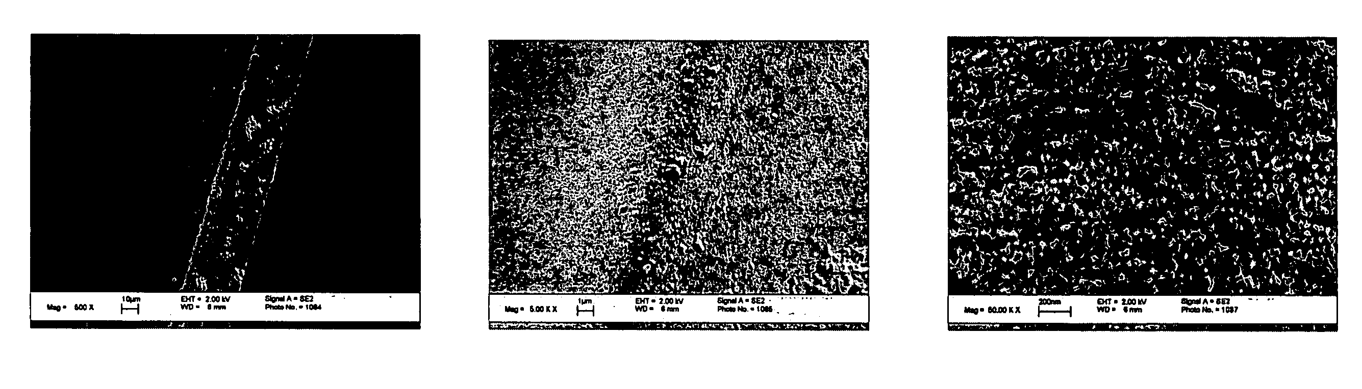
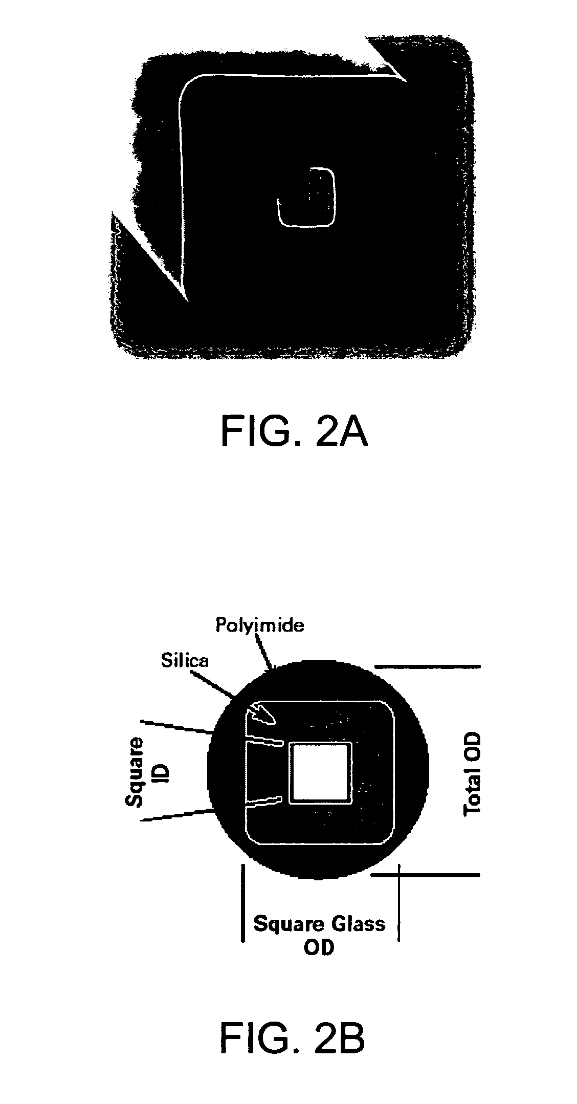
[0054] The fibers shown in FIG. 4 were made in a four-fold axial symmetric capillary (square cross-section as seen in FIG. 2) using a poly(Trimethylolpropane Triacrylate-co-ethylene dimethacrylate) System. The prepolymer solution was flowed into the UV-exposed region of a capillary at a low, constant flow rate. The pre-polymer system used in this synthesis was a PIPS solution so, at a point determined by the thermodynamics of the system, there was a nucleation and growth phase separation that occurred. This phase-separation created the porous structured fibers seen in FIG. 4. This synthesis can also be accomplished in the same manner using a microfluidic chip. The fiber seen in the image can be seen to be composed of partially coalesced nano-particles. The surfaces of these fibers show a roughly uniform level of surface roughness and a high level of porosity. The protocol listed below was conducted 25° C. and 1 atm. The polymer flow was induced using a low-flow r...

example 2

Another Example of a Prepolymer System

[0062] Another prepolyer system that can be utilized in the same manner as in Example 1 is composed of 0.96 g of Ethylene Glycol Dimethacrylate (EGDMA, δD=17.2 J1 / 2 cm−3 / 2, δP=0.2 J1 / 2cm−3 / 2, δH=8.8 J1 / 2cm−3 / 2, δ=19.3 J1 / 2cm−3 / 2), 1.301 g of Hydroxyethylmethacrylate (HEMA, δD=17.8 J1 / 2cm−3 / 2, δP=0.4 J1 / 2cm−3 / 2, δH=14.8 J1 / 2cm−3 / 2, δ=23.2 J1 / 2cm−3 / 2), 24 mg of AIBN, and 3.6 g of a porogenic solvent in a UV-initiated polymerization reaction. The solvent system used is Methanol (MeOH, δD=15.2 J1 / 2cm−3 / 2, δP=12.3 J1 / 2cm−3 / 2, δH=22.3 J1 / 2cm−3 / 2, δ=29.2-29.7 J1 / 2cm−3 / 2) and Hexane (δD=14.8 J1 / 2cm−3 / 2, δP=0 J1 / 2cm−3 / 2, δH=0 J1 / 2cm−3 / 2, δ=14.8-14.9 J1 / 2cm−3 / 2). In the pure methanol solvent system the median pore size is 54 nm, in the MeOH / EtOH (50 / 50) system the median pore size is 51 nm, and in the MeOH / Hexane (50 / 50) system the median pore size is 7959 nm. Polymerized EGDMA shifts to a higher solubility parameter δ=22.5 J1 / 2cm−3 / 2 (δD=20 J1 / 2cm−3 / 2, ...

example 3

Steps in a Method of Micromold Operation

[0063] This example embodies one of the three preferred methods of creating microcarriers. Micromolding provides the ability to create thousands of microcarriers in one synthesis cycle. This method of fabrication utilizes two microfabricated fused quartz wafers as molds for UV synthesis of the desired cubical microcarriers. This method includes the following steps:

1) Fabrication (UV lithography, laser processing, etc.) of two replicate surfaces.

2) When the surfaces are glass, the surfaces are treated with a material (e.g., flourosilane) that deactivates the surface, so the polymer does not adhere to the surface of the mold.

3) The molds are filled with the prepolymer solution

a. With Interconnecting Channels

b. The chips are aligned and the assembly is closed

i. The prepolymer solution is degassed prior to injection into the assembly

ii. The assembly is then filled with a prepolymer from a central port

iii. Without Interconnecting C...


PUM

PropertyMeasurementUnit
sizeaaaaaaaaaa
sizeaaaaaaaaaa
molecular weightaaaaaaaaaa

Abstract

Methods for producing and using polymeric microstructures having a pre-determined geometry (e.g., rectangular prism, cube), and pre-determined surface characteristics are disclosed herein. The polymeric microstructures described herein are particularly useful as microcarriers in cell culture applications because they provide high surface areas, and improved surface/volume ratios over currently available microstructures, and can be manufactured to have pre-determined physiochemical characteristics (e.g., substrate curvature, texture, shape, porosity, surface chemistry) to optimize compatibility with a pre-determined type of cell (e.g., bacterial, animal, mammalian, human) to be cultured. The polymeric microstructures described herein are also particularly useful in tissue engineering (e.g., bone engineering) applications.

Description

CROSS-REFERENCE TO RELATED APPLICATIONS [0001] This application claims priority from U.S. provisional patent application Ser. No. 60 / 655,177 filed Feb. 22, 2005, and U.S. provisional patent application Ser. No. 60 / 715,416 filed Sep. 9, 2005.FIELD OF THE INVENTION [0002] The invention relates generally to the fields of polymer science and microstructure technology. More particularly, the invention relates to polymeric microstructures having a particular geometry (e.g., a regular or irregular polyhedron such as a rectangular prism or a cube), and particular surface characteristics (e.g., texture, topology, chemistry); and methods for producing and using such microstructures. BACKGROUND OF THE INVENTION [0003] Large-scale cell culture typically involves using a bioreactor to grow cells in suspension in a liquid medium. To facilitate growth of anchorage-dependent cells in a bioreactor, microstructures can be added to provide a substrate to which the cells can adhere. Conventionally, sph...

Claims


Application Information

Patent Timeline
Patent Type & Authority Applications(United States)
IPC IPC(8): A61K8/02
CPCB29C39/006C08F6/005D01F6/36D01D5/38D01D5/247
Inventor STEPHENS, CHRISENGLEMAN, PETER GREGORYBENSON, ROBERTO
Owner UNIV OF TENNESSEE RES FOUND
Why Eureka
Try Eureka