Plasma processing apparatus and method

a processing apparatus and technology of plasma, applied in the field of plasma processing apparatus, can solve the problems of reducing the yield of products, physical polishing, and contaminating the outer edge of the wafer, so as to prevent contamination and improve production yield, the effect of easy assembly

Inactive Publication Date: 2006-11-23
SEKISUI CHEM CO LTD
View PDF1 Cites 12 Cited by
  • Summary
  • Abstract
  • Description
  • Claims
  • Application Information

AI Technical Summary

Benefits of technology

[0023] According to this first feature, clearances can be formed each between the respective inner and outer annular electrodes and the holder. This makes it easy to carry out the removing and assembling operation with ease. Moreover, since the positional adjustment, i.e., centering of the electrode with respect to the corresponding holder can be made by the pushers, precision of the attaching position can satisfactorily be obtained.
[0072] It is desirous that the wafer is supported by a wafer support part which is abutted only with a back surface of the wafer and the blow-off operation is carried out while rotating the wafer support part and therefore, rotating the wafer about a center axis of the wafer. Owing to this arrangement, the wafer can be avoided from being contacted at the outer surface, contamination, etc. can reliably be prevented from occurrence, and the processing efficiency can be enhanced.

Problems solved by technology

This not only results in inconvenience at the time of polishing the film surface but also tends to cause contamination due to peel-off.
In the case of deposition according to PE-CVD and LP-CVD, it is seldom that the film becomes large in thickness at the outer edge of the film, but there is a possibility that crack occurs when the outer edge of the wafer is accidentally contacted during the transferring process, thus resulting in contamination.
However, it is said that the low dielectric film is smaller in mechanical strength than SiO2 and therefore, that the film formed on the outer edge of the wafer is liable to be a cause for occurring contamination in a physical polishing process such as CMP (chemical mechanical polishing).
Such contamination is liable to become the cause for such an inconvenience as short circuit of the wiring, and this often results in reduced yield of product.
As the miniaturization of semiconductor is developed, the wiring is reduced in thickness and thus readily subject to the adverse effect of contamination.
However, the method for removing a film on the outer edge of a wafer according to the above-mentioned wet etching technique has such inconveniences that not only the film formed on the outer edge but also the film formed on the main area become brittle by moisture of the etching liquid and a huge cost is required for processing the exhaust liquid.
Although it is desirous that the outer end face of the film is formed in a slope configuration in order to disperse stress at the time of physical polishing, the outer end face of the film becomes a sharpened edge-like configuration according to the wet etching technique, thus making it difficult to obtain the slope-like configuration.
If some clearance is not formed between each electrode and the holder at that time, the detaching / assembling operation is difficult to carry out.
However, if some clearance should be provided in a double annular electrode structure, precision of the attaching position of the electrodes would readily be disordered and the centers of the inner and outer electrodes would be displaced from each other.
On the other hand, in case the electrodes are annular, it is not easy to form a cooling passage for temperature adjustment at the inside of the electrodes.
In case the contact area with the electrode is small, fully satisfactory cooling efficiency (temperature adjusting efficiency) is unobtainable.
Moreover, for example, in the double annular electrode structure, in case a coolant tube extending in the inner peripheral surface is disposed at the inner peripheral surface of the inner electrode and a coolant tube extending in the peripheral direction is disposed at the outer peripheral surface of the outer electrode, if the coolant tubes are unchanged in curvature along the peripheral surfaces of the electrodes and non-expansible / non-contractible, the disassembling / assembling operation is encountered with difficulty at the time of maintenance.
The used processing gas and the byproduct film generated by etching are required to be removed rapidly because if not, they can prevail such adverse effect as staying on the wafer.
However, in case the blow-off port and exhaust port of the processing gas are located overly away from each other, the gas flow is difficult to control and an exhaust pump having a large capacity is required.
In case an exhaust passage is formed in the frame of the apparatus, there is such a fear that the inner peripheral surface of the frame gets corrosion.
Any attempt to make the frame from a corrosion-resistant metal results in high cost.
H05-82478 has such disadvantages that a chip located at an area sandwichingly held by the O-ring of the pair of chucking means is liable to be damaged, and that the film formed on this area is liable to split, thus generating fine dusts, which can be a cause for contamination.
Moreover, since a housing for forming an annular closed clearance is required radially outwardly of the wafer, the apparatus becomes large in size.
This makes it difficult to employ as a replacement of the wet etching mechanism of the conventional spin coater.
This makes it difficult to control the flow of those gases, and thus, it is difficult to remove the film formed on the outer edge with precision.
If any attempt is made to stop the carrier gas, there is such a fear that the plasma enters not only the outer edge of the wafer but also the area which is located at the inner side of the outer edge and which is not to be processed.
Thus, there is a possibility that even the film formed on the area which is not to be removed is removed.

Method used


Image

  • Plasma processing apparatus and method
  • Plasma processing apparatus and method
  • Plasma processing apparatus and method

Examples


first embodiment

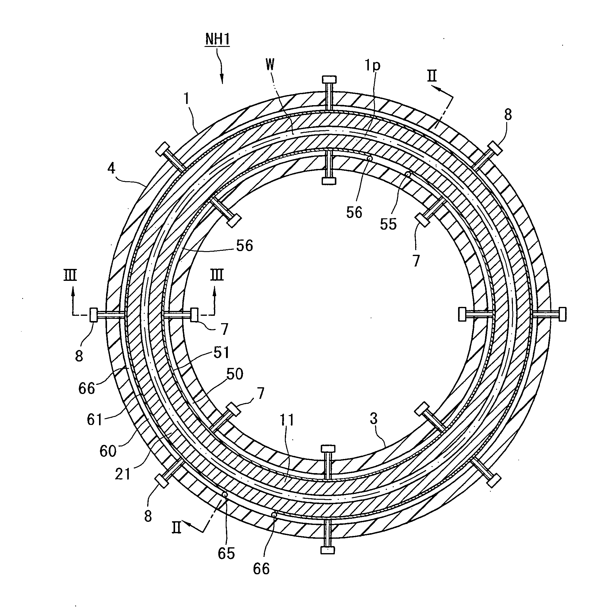
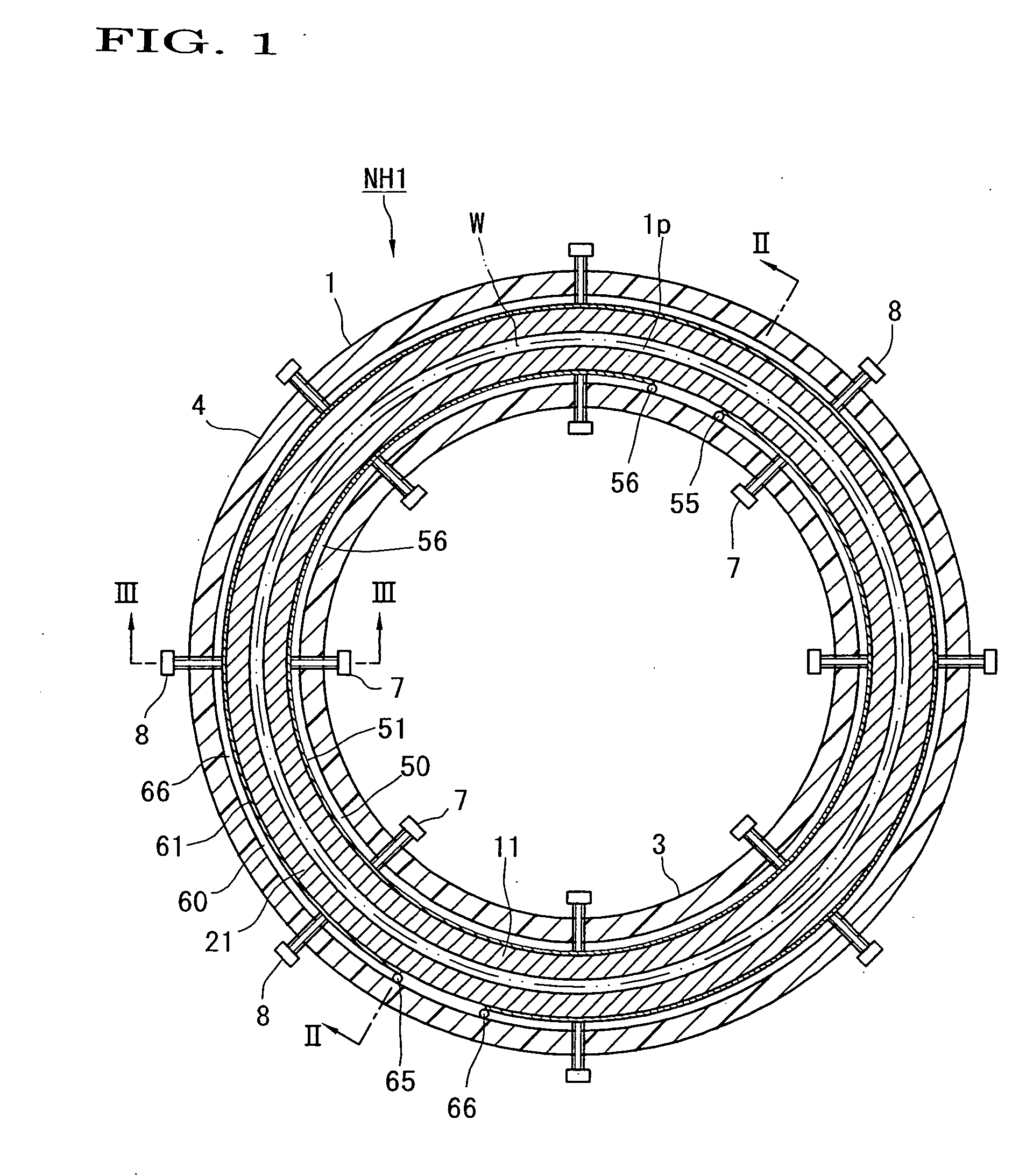
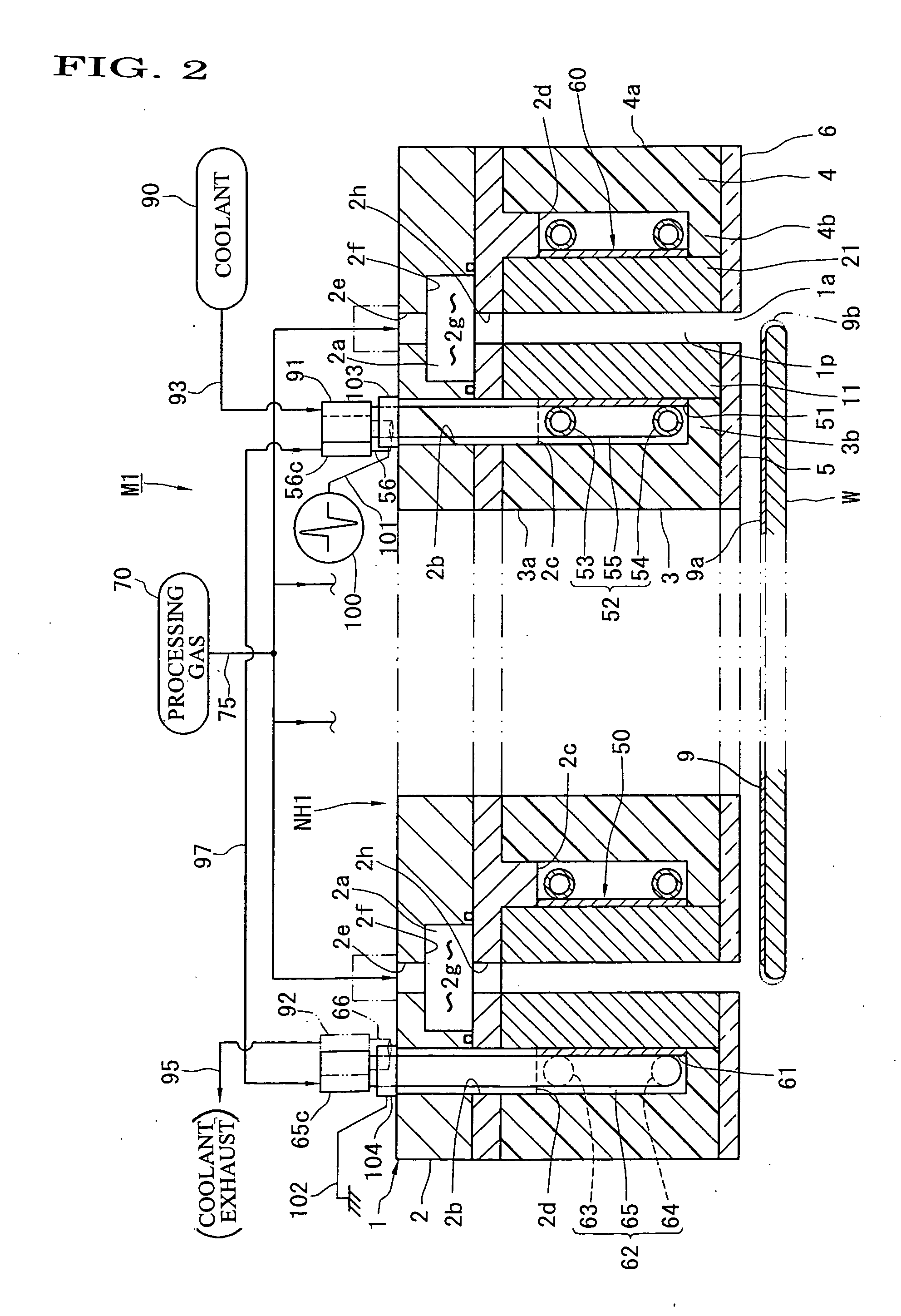
[0097] The first embodiment will be described. FIGS. 1 and 2 show a normal pressure plasma etching apparatus M1 (plasma processing apparatus) in which a semiconductor wafer W is used as an object to be processed. The wafer W will be described first. As shown in FIGS. 1 and 2, the wafer W is formed in a disc-like configuration by semiconductor such as silicon. On an upper surface or outer surface of the wafer W, a film 9 such as a photoresist is formed, for example, by spin coater. This film 9 covers the entirety of the upper surface of the wafer W and extends up to the outer edge, i.e., the outer edge part of the upper surface and the outer end face. Should this film 9b occupying the outer edge (imaginary line of FIG. 2) be allowed to remain, it could be an interference in the succeeding polishing process or it could be a cause for generating particles in the process for holding the outer edge. Thus, the wafer W is sent to the normal pressure plasma etching apparatus M1 after it is ...

second embodiment

[0145] As shown in FIGS. 5 and 6, in the second embodiment, plasma etching of a film 9b formed on the outer edge of a semiconductor wafer W is carried out by a normal pressure plasma etching apparatus. The normal pressure plasma etching apparatus M2 comprises an annular nozzle head NH2 in a plan view, a pulse power supply 100 (electric field imparting means), a processing gas supply 70, a suction pump 80 (suction device), and a coolant supply 90 (temperature adjusting medium supply). The nozzle head NH2 comprises an inner electrode structure 10, an outer electrode structure 20, an insulating holder 30 for covering those electrode structures 10, 20, and a metal-made (conductive) frame 40 for covering this holder 30. Those component elements 10, 20, 30, 40 each have an annular configuration.

[0146] As best shown in FIG. 7, the inner electrode structure 10 comprises an annular electrode 11 (inner electrode), and an annular metal-made passage forming member 15 concentrically arranged ra...

third embodiment

[0175]FIG. 10 shows a third embodiment of the present invention. In the third embodiment, the outer edge (part to be processed) of the semiconductor wafer W is plasma etched by a normal pressure plasma etching processing apparatus M3. The film (indicated by an imaginary line in FIG. 12) as an object to be processed formed on the outer edge of the wafer W is denoted by reference numeral 92b and the film (indicated by a solid line in FIG. 12) as an object not to be processed formed on the main area excluding the area denoted by reference numeral 92b of the upper surface is denoted by reference numeral 92a.

[0176] The normal pressure plasma etching apparatus M3 will be described.

[0177] As shown in FIG. 10, the normal pressure plasma etching apparatus M3 comprises a nozzle head N13, a processing gas supply 70 and a voltage imparting device 100 which are connected to the nozzle head NH3, and a rotary stage 140 (rotary device, air-stream forming device, and wafer support device). The rot...


PUM

PropertyMeasurementUnit
pressureaaaaaaaaaa
frequencyaaaaaaaaaa
electric field intensityaaaaaaaaaa

Abstract

A nozzle head NH of a plasma processing apparatus comprises an annular inner holder 3, an annular inner electrode 11 surrounding this holder 3, an annular outer electrode 21 surrounding this electrode 11, and an annular outer holder 4 surrounding this electrode 21. The inner holder 3 is provided with a plurality of bolts 7 spacedly arranged in the peripheral direction and adapted to push the inner electrode 11 radially outwardly. The outer holder 4 is provided with a plurality of bolts 8 spacedly arranged in the peripheral direction and adapted to push the outer electrode 21 radially inwardly. Owing to this arrangement, the operation for disassembling, assembling and centering the annular electrodes 11, 21 can be carried out with ease.

Description

TECHNICAL FIELD [0001] This invention relates to a plasma processing apparatus and a method thereof, in which various surface processing, such as workpiece (object to be processed) etching, chemical vapor deposition (CVD), cleaning, ashing, surface modification and the like are carried out by plasmatizing a processing gas and applying the plasmatized gas to a workpiece such as a semiconductor wafer. BACKGROUND ART [0002] A semiconductor wafer is, for example, subjected to an etching process via deposition process (film forming process) using a spin coater or the like. The spin coater is a device for forming a thin film such as an insulating film and a photoresist film on the semiconductor wafer. The semiconductor wafer is rotated and a material liquid is dropped on to a central part of an upper surface (front surface) of the wafer, so that the material liquid is spread over the entire surface by centrifugal force. By doing this, a thin film covers not only the main area (the inner s...

Claims


Application Information

Patent Timeline
Patent Type & Authority Applications(United States)
IPC IPC(8): H01L21/306C23C16/00H05H1/24B01J19/08C23C16/509H01J37/32H01L21/3065
CPCC23C16/5093H01J37/32009H01L21/3065H01J37/32724H01J37/32541H01L21/205H01L21/304H01L21/306
Inventor NOGAMI, MITSUHIDEMIYAMOTO, EIJI
Owner SEKISUI CHEM CO LTD
Why Eureka
Try Eureka