

Photocatalyst and use thereof
a photocatalyst and photocatalyst technology, applied in the field of photocatalysts, can solve the problems of 5% of sunlight, limited or zero visible light activity of the photocatalyst, poor efficiency and/or stability
- Summary
- Abstract
- Description
- Claims
- Application Information
AI Technical Summary
Problems solved by technology
Method used
Image

Examples
example 1
Synthesis of CdS-TiO2 Composite Photocatalyst
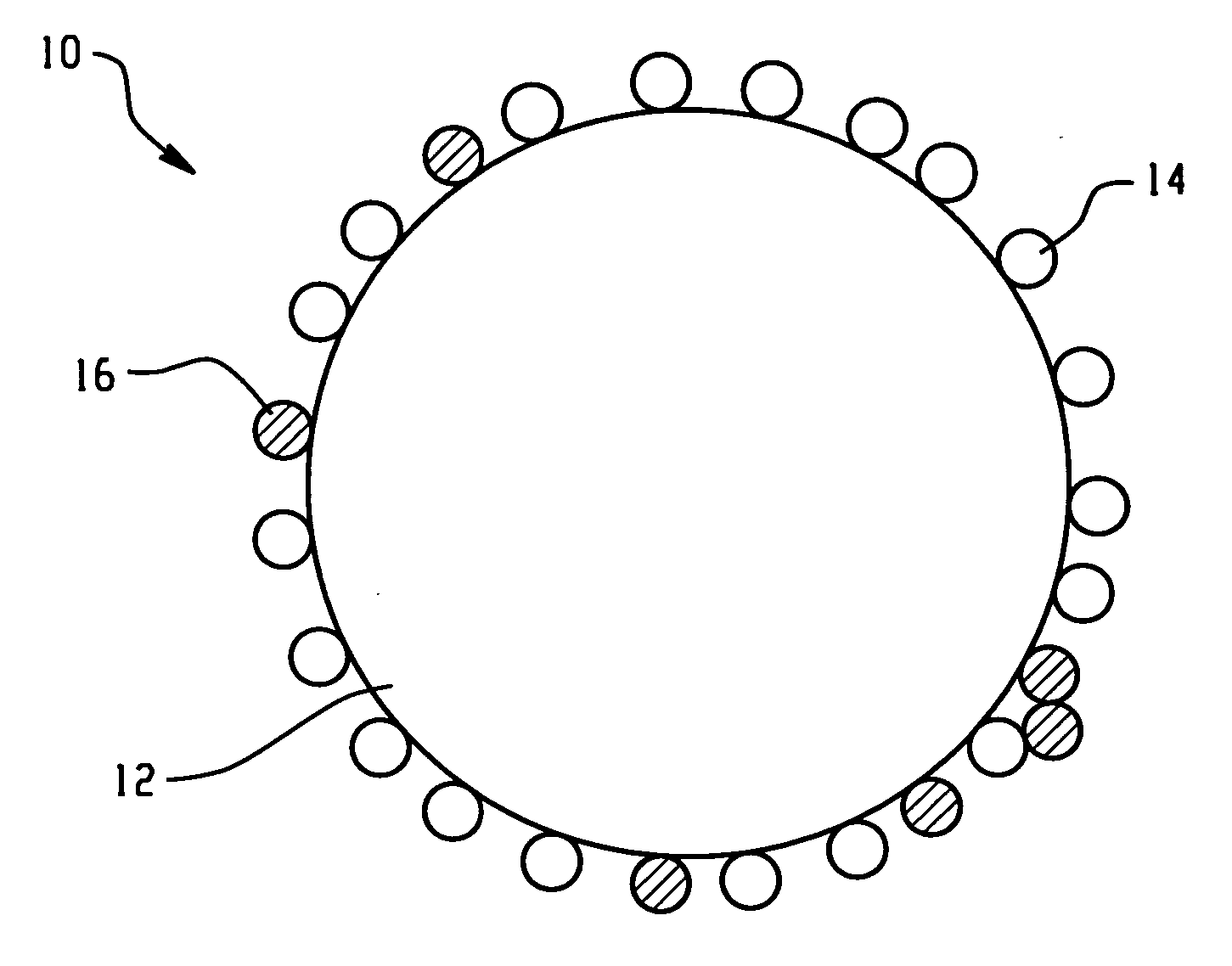
[0045] A stoichiometric amount of an aqueous solution of Na2S was added dropwise to a solution of Cd(NO3)2 dissolved in isopropyl alcohol. The dried, filtered CdS precipitate was calcined at about 1073 degrees Kelvin (K), or 800 degrees Celsius (° C.), for about 1 hour under He to improve its crystallinity. The crystalline CdS was stirred in isopropyl alcohol and tetra-titanium isopropoxide in water was added dropwise such that the molar ratio of Ti to CdS was 4 to 1. The dried, filtered composite powder was calcined at about 673 K for between about 1 to about 3 hours in air to improve the crystallinity of the TiO2 phase.
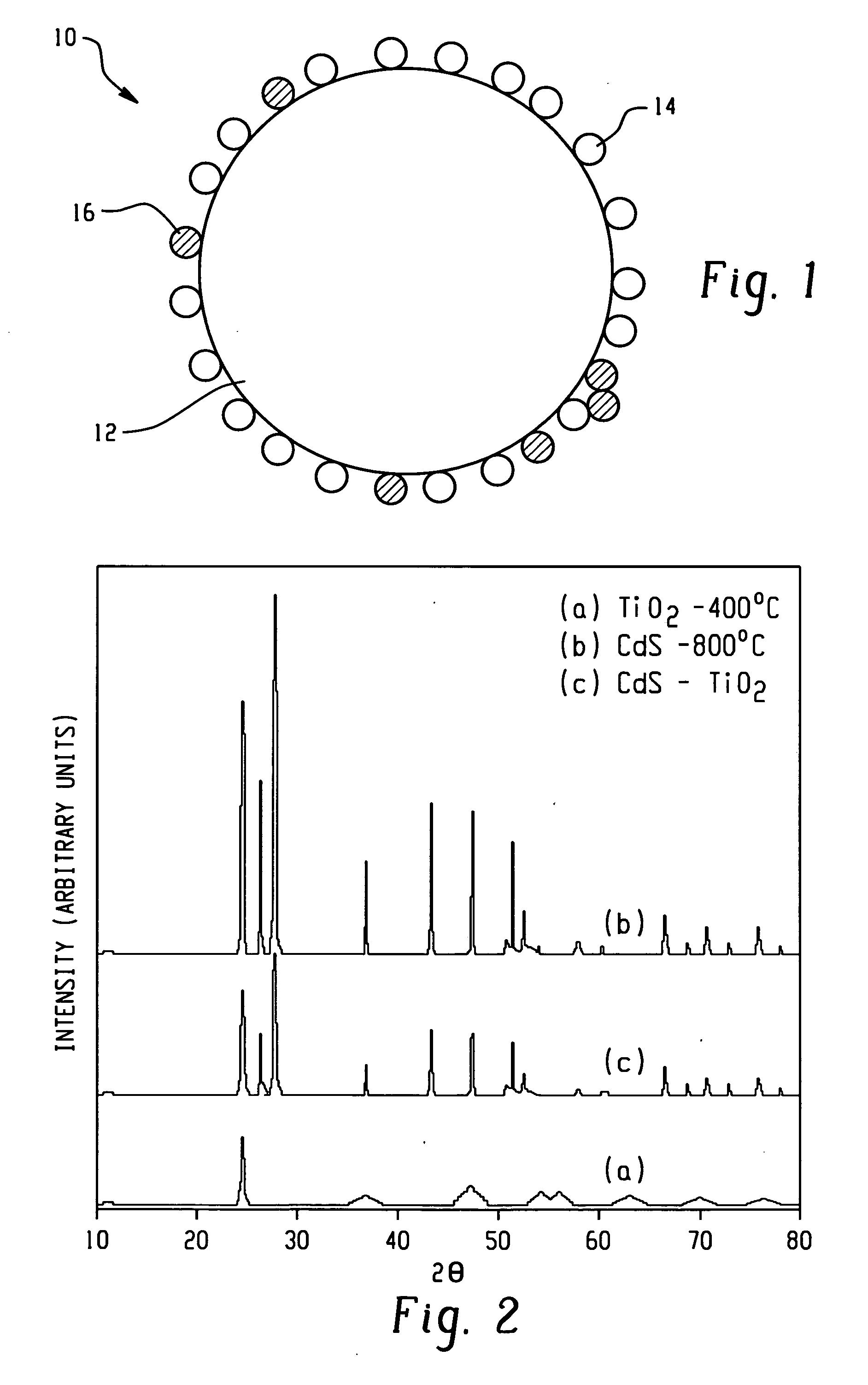
[0046] The products were first characterized by powder X-ray diffraction (PXRD). FIG. 2 shows representative PXRD patterns, taken with a Mac Science Company (M18XHF) X-ray diffractometer (Cu Ka radiation), of (a) TiO2 calcined at 400° C. in air, (b) CdS calcined at 800° C. for 1 hour under He, and (c) the CdS-TiO2 compo...
example 2
Hydrogen Production Using CdS-TiO2 Composite Photocatalyst
[0049] About 1 weight percent (wt %) of Pt was deposited onto the composite photocatalyst using a photodeposition technique under visible light. The photocatalytic reactions were carried out at ambient temperature and pressure in a closed circulation system using a 350 Watt (W) Hg-arc lamp equipped with a longpass or UV cutoff filter to remove light having a wavelength (□) below 420 nm. The reactions were performed with about 0.1 grams (g) of photocatalyst in about 100 milliliters (mL) of an aqueous solution containing about 0.1 mole / liter (M) Na2S and about 0.02 M Na2SO3. The amount of H2 produced was determined using gas chromatography with argon as the carrier gas, a 5 Angstrom (Å) molecular sieve column, and a thermal conductivity detector. Hydrogen levels of about 1700 micromoles / hour (μmol / h) were achieved.
example 3
Comparison of Photocatalyst Performance
[0050] In this example, the CdS-TiO2 composite photocatalyst was compared to a series of single phase CdS photocatalysts. The average hydrogen evolution rates during a 5-hour period, as well as other physical properties, for each of the photocatalysts are shown in Table 1. It is clear that with respect to the three CdS samples, as the crystallinity of the CdS increased (i.e., calcination temperature increased), the rate of hydrogen production increased.
TABLE 1Photocatalyst properties.Surface areaBandgap EnergyH2 evolution ratePhotocatalyst[m2 / g]Eg(eV)λab(nm)[μmol / h]CdS (Aldrich)9.62.2555032CdS-400° C.28.82.1857025CdS-800° C.2.18570347CdS—TiO297.02.255501562composite
[0051]FIG. 5 graphically illustrates the results of the photocatalytic reaction, as described in Example 2, for a sample of the CdS-TiO2 composite photocatalyst and a sample of 800° C.-calcined CdS, with the exception that isopropyl alcohol was used as the solvent for the 800° C.-...
PUM
| Property | Measurement | Unit |
|---|---|---|
| Percent by mass | aaaaa | aaaaa |
| Area | aaaaa | aaaaa |
| Nanoscale particle size | aaaaa | aaaaa |
Abstract
Description
Claims
Application Information