Use of a non-corrosive, martensitically hardening steel

a martensitic hardening, non-corrosive technology, applied in the field of stainless steels and precipitation hardenable, can solve the problems of inability to apply tools, difficult to apply to rotary tools with complicated geometry, and tools are sensitive to the bending loads applied in practical use, and achieve high corrosion resistan

Inactive Publication Date: 2007-01-04
SANDVIK INTELLECTUAL PROPERTY AB
View PDF2 Cites 15 Cited by
  • Summary
  • Abstract
  • Description
  • Claims
  • Application Information

AI Technical Summary

Benefits of technology

[0025] As the corrosion results suggest that the material has a high corrosion resistance under both acid and alkaline application conditions, it is to be assumed tha

Problems solved by technology

Because of the high hardness of the steel, further working had to be restricted to a minimum.
The problem of workability was solved in this case with the help of the special manufacturing process, but this cannot be applied to tools, especially rotary tools with complicated geometry.
Because of this extreme length/diameter ratio and the resulting unfavourable moment distribution, such tools are very sensitive to the bending loads applied in practical use.
A slight bending, barely visible to the naked eye, of the drill can result in its generally running untrue and being unbalanced when next prepared by the operator or next used.
Because of the frequently very high rotation speeds this results, in practice, in the drill bits breaking off during operation.
This means not only that the drills have a short life and must frequently be replaced for reasons of safety, but also that there is a substantial risk of injury for operator, patient and bystanders who may be hit by flying parts of tools, as well as a substantial cost factor.
According to the Medical Products Law, tools with small dimensions in particular are designated disposable products by manufacturers, which represents an additional cost for the user.
After the tools have been used once their use on a second occasion is no longer allowed,

Method used


Image

  • Use of a non-corrosive, martensitically hardening steel
  • Use of a non-corrosive, martensitically hardening steel
  • Use of a non-corrosive, martensitically hardening steel

Examples


Embodiment Construction

[0011] The object of the present invention is to overcome the aforementioned problems and disadvantages of the state of the art.

[0012] This object is achieved according to the invention through the use of a precipitation-hardenable, martensitic, rustless chrome nickel steel with the following composition (in wt.-%):

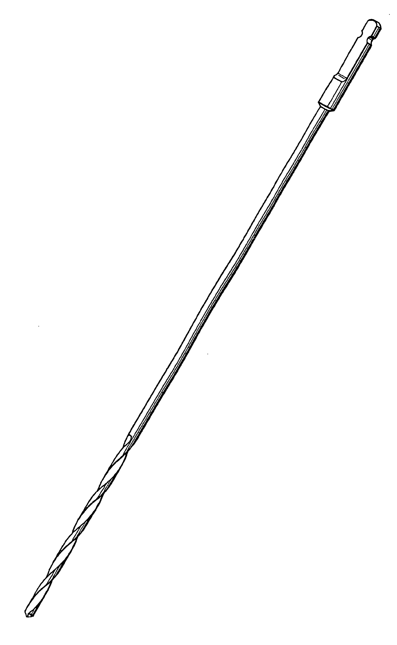
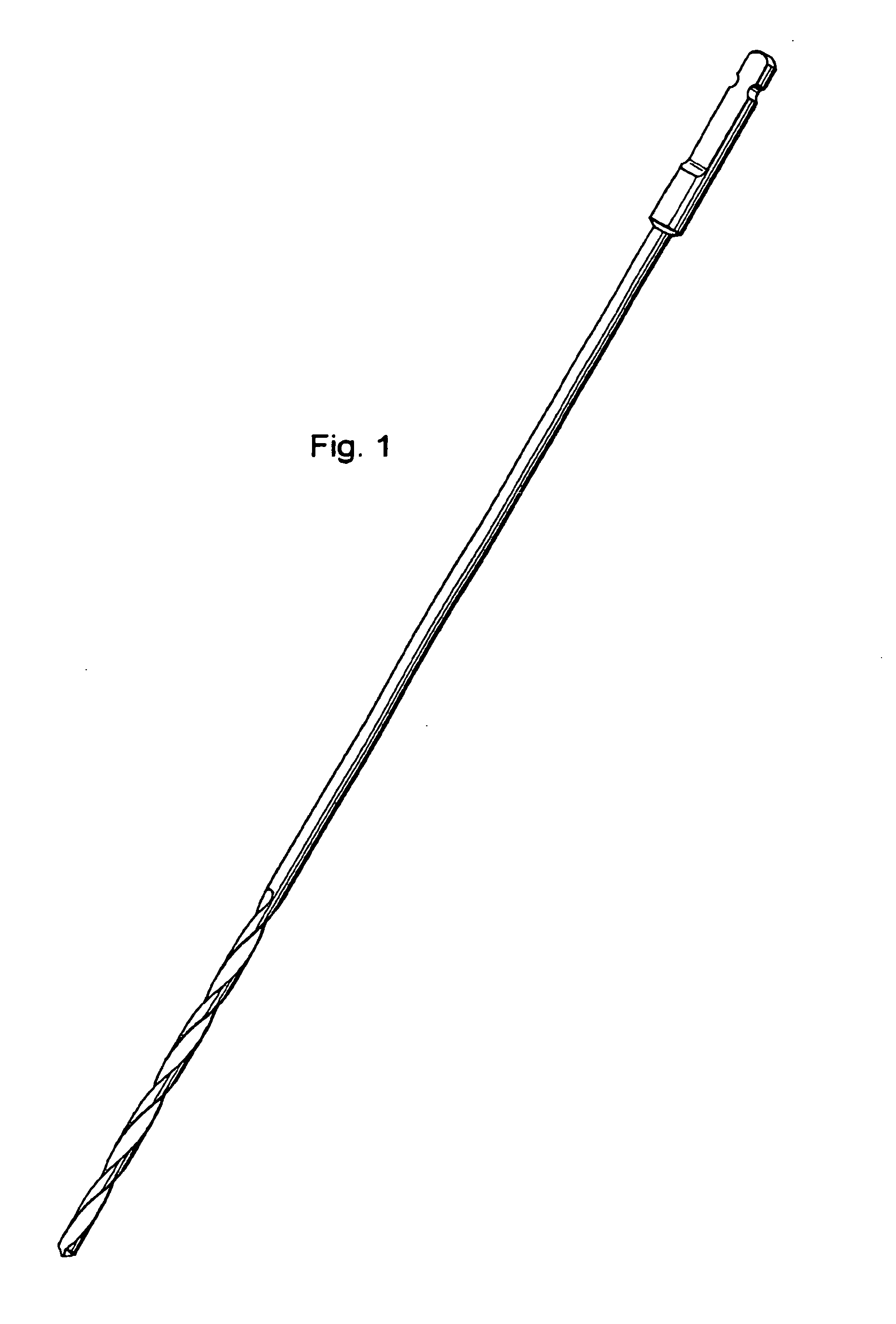
Chromium10 to 14Nickel7 to 11Molybdenum0.5 to 6Copper0.5 to 4Aluminium0.05 to 0.55Titanium0.4 to 1.4Carbon + nitrogenup to 0.3Sulphurless than 0.05Phosphorusless than 0.05Manganeseup to 0.5Siliconup to 0.5Tantalum, niobium, vanadium andeach up to 0.2tungstenCobaltwhere appropriate up to 9.0Boronwhere appropriate 0.0001 to 0.1[0013] the remainder comprising iron and customary impurities, for the manufacture of machine-operated rotary tools. This object according to the invention is further achieved by the provision of machine-operated rotary tools which are made from precipitation-hardenable, martensitic, rustless chrome nickel steel with the aforementioned composition....


PUM

PropertyMeasurementUnit
Fractionaaaaaaaaaa
Fractionaaaaaaaaaa
Fractionaaaaaaaaaa

Abstract

The aim of the invention is to produce mechanically driven rotary tools, preferably boring, milling, grinding and cutting tools which are stable, non-corrosive and biocompatible and also have high mechanical strength properties, in conjunction with good ductility properties. To this end, the invention relates to the use of a precipitation-hardenable, martensitic, stainless chromium-nickel steel having the following composition (in weight %): 10 to 14 of chromium; 7 to 11 nickel; 0.5 to 6 of molybdenum; 0.5 to 4 of copper; 0.05 to 0.55 of aluminium; 0.4 to 1.4 of titanium; up to 0.3 of carbon and nitrogen; less than 0.05 of sulphur; less than 0.05 of phosphorus; up to 0.5 of manganese; up to 0.5 of silicon; respectively up to 0.2 of tantalum, niobium, vanadium and wolfram; and optionally up to 9 of cobalt; optionally 0.0001 to 0.1 of boron; the reminder consisting of iron and common impurities.

Description

TECHNICAL FIELD [0001] The invention relates to a novel use for precipitation-hardenable, martensitic, stainless steels for the manufacture of rotary tools for applications with high requirements as regards a combination of high hardness and ductility as well as corrosion resistance, such as drilling, milling, grinding and cutting tools. BACKGROUND AND TECHNICAL PROBLEM POSED [0002] Precipitation-hardenable, martensitic, stainless steels are known from WO 93 / 07303. In this a composition of a stainless steel is described which has a very high strength with simultaneously good ductility. This steel is described as being particularly suitable for the manufacture of injection cannulae, dental instruments and medical instruments on the basis of wire and strip material produced from the named types of steel. Because of the high hardness of the steel, further working had to be restricted to a minimum. [0003] In WO 01 / 14601 A1 a process is described for the manufacture of parts with complic...

Claims


Application Information

Patent Timeline
IPC IPC(8): C22C38/42C22C38/52C22C38/00C22C38/06C22C38/44C22C38/50
CPCC22C38/004C22C38/06C22C38/50C22C38/44C22C38/42
Inventor BLANKE, BERND
Owner SANDVIK INTELLECTUAL PROPERTY AB
Why Eureka
Try Eureka