Sparse media edi apparatus and method

a technology of edi and media, applied in the field of electrodialysis, can solve the problems of inefficiency of operation, difficulty in uniform filling of thin cells, and inability to meet the needs of patients, and achieve the effects of enhancing fluid shear effect, ensuring stability, and good membrane conta

Inactive Publication Date: 2007-03-08
IONICS INC
View PDF3 Cites 38 Cited by
  • Summary
  • Abstract
  • Description
  • Claims
  • Application Information

AI Technical Summary

Benefits of technology

[0034] In some embodiments, a screen or mesh is used to fix or constrain movement of the filling. Such constructions are especially preferred in sparse fillings, and most preferably when the filling is constituted by a bed of isolated or non-contiguous beads of exchange material. Unlike conventional EDI mesh constructions wherein a screen serves essentially as a spacer to maintain an open flow path while separating the cell membranes by a defined distance, the fibers of the mesh, forming the edges of each small corral, are effective to segregate the resin particles in the cell against migration. When the layer is more than one bead deep (for example when it is between 1 and about 2 beads deep), the screen filaments may also function to support the resin particles. The packing density is relatively low-well under 80%, and may be relatively uniform at a level of about 40% to about 65%, when a mono- or bi-layer is used, and as low as 15-20% when a sparse layer of non-contiguous beads is used. Use of a screen with a small open lattice to support and / or restrain the particles allows granular beds less than a few grains thick to be dependably formed and robustly maintained in position. Because the filling has relatively few grains, an open (highly permeable) packing is obtained and good membrane contact may be achieved even when inexpensive ungraded ion exchange resins with a wide particle size distribution are employed. With uniform size resins, strict monolayers may be readily achieved, while with resins having Gaussian, multimodal or broad particle size distribution, mono- or bilayer thickness may be dependably achieved in cells up to several times the mean particle dimension while achieving and maintaining a stochastic uniformity in distribution of the sparse filling.
[0035] In operation, when fluid flows through the EDI cells so constructed, the presence of the mesh fiber segments extending in different directions and / or different level of the channel further serves to deflect flow across the thickness dimension of the cells in a serpentine fashion, enhancing fluid shear effects for ion capture and removal at both the cation and anion membrane sides of the channel. In general, the presence of single exchange beads directly contacting and supporting the membranes results in a construction in which each bead acts as a “pillar” in the flow path that both supports the membrane and provides unidirectional ionic conduction to one or the other adjacent membranes, e.g., of like ion exchange type (in the dilute cells) or a uniformity of current flow (in the concentrate cells).
[0036] In another general form of construction, the EDI apparatus of the invention is configured as a spiral-wound EDI module rather than a stack. In the spiral embodiments, the dilute cells, concentrate cells or both are configured with a sparse filling of exchange material as described above. Modules in accordance with the invention may be readily manufactured in spiral form, and the thin cells so constructed allow a large number of spiral windings to be achieved in each module while assuring a uniform current distribution free of voids and hot spots at which malfunction such as blockage, scaling, or other undesirable operation contributing to malfunction, aging or premature failure might occur. Advantageously, for such spiral module constructions, great manufacturing efficiencies are achieved. The ion exchange membrane may be covered with a coating of beads as a bulk coating process in a continuous run, and cells may be formed by edge-sealing the membranes to form one long closed envelope. One or several of the envelopes so constructed may then be wound and closed in a cartridge. Thus, spiral modules may be assembled from a coated membrane which carries sparse bead, sandpaper-like, on its surface, forming cells as spiral-wound envelopes communicating with respective dilute and concentrate manifolds. The electric field is established radially, e.g., between a center electrode and a circumferential electrode as in the prior art, and the center electrode may comprise a pipe that also constitutes the supply or the brine manifold. Constructions may be configured for axial or radial flow.
[0037] Sparse fillings of the invention may be implemented with only the concentrate cells, or only the dilute cells having a sparse bead distribution. In that case, the cells of opposite type (dilute or concentrate) may be like those of prior art EDI devices—e.g. with thicker and bead-filled dilute cells, or with empty concentrate cells or with thicker and bead-filled concentrate cells (with or without a screen spacer). In units of the invention, when both dilute and concentrate cells are to have a sparse bead distribution, the dilute cells and concentrate cells need not have the same type of bead filling. For general demineralization applications, it is generally preferred that the dilute cells include exchange resin of both types, either mixed, or layered or in a sequence of stripes. However, some embodiments of the invention may have monotype exchange resin in the dilute cells to effect or enhance the removal of particular ions and / or to provide substantially acidic or basic streams during all or a portion of the processing. In a number of embodiments, the concentrate cells may have a single type of resin, and the resin may be selected to have a specific strength or quality in view of the fluid processing. By way of example, an anion resin may be used in the concentrate cells for enhanced resistance to scaling, or a cation resin may be used for particular fluids for which its resistance to oxidation or to degradation by chlorine is advantageous. These properties are also advantageous when used near the electrode chambers, so such single-type resin may also be used in the catholyte or anolyte cell or proximate portion of the stack. Similarly, a monotype resin may be selected for use in concentrate cells for enhanced conductivity, heat resistance or other property. It is also not required that all cells of a given type be sparsely filled; a unit may employ a first set of cells of conventional thickness and filling, and a second set of cells having a sparse filling.

Problems solved by technology

Uniform filling of the thin cells may be technically challenging, although some modular “envelope” constructions have long addressed this by simply designing the cells of an EDI stack as sealed modular compartment subunits, each compartment having several ribs or dividers forming a number of closed sub-compartments.
However, the exchange bead size, and the size relative to cell dimensions, impose certain limitations on the overall deionization process, and difficulties may arise in the process of filling the cells in the stack, or in maintaining a distribution or uniformity of cell filling over time, or in maintaining suitable flow impedance.
However, in operation a number of generally acceptable designs have been found to suffer from problems such as localized heating, scaling, or irregular, locally excessive or deficient current distributions that contribute to such conditions or impair product quality.
However, these dimensional constraints necessarily result in a certain inefficiency of operation due to the above-mentioned discontinuous transport mechanism involving ion release and water-splitting at grain boundaries.
Other inefficiencies exist in typical current EDI stack designs.
The loading of removed ions present in the resin is quite large, and when an EDI device is operated in a reversal mode, displacement and other processes may result in prolonged bleeding that can impair operation or require phased diversion of product or concentrate flows to maintain quality.
Moreover, filling with smaller particles, such as filling of an assembled stack by flow-deposition of a particle slurry, or assembly-line filling of individual cell “envelopes” before assembly of the stack, may result in irregular or unanticipated segregation or sedimentation by resin type, or to complete blockage or irregular packing compared to larger cells with larger beads filled by conventional methods or transported in larger passages; or assembly of such a non-bulked device may prove to be too costly to produce a competitive device.
Non-uniform distribution of resin or variations in internal flow can result in regions of excessive current, regions of low current, localized regions of extreme pH or concentrations of particular ions, and various scaling or related problems.
This would reduce the attainable flow rate for a given operating pressure, or pressure differential, and might possibly result in stagnation, polarization and scaling, or introduce other deleterious effects.
The construction of flow cells by large parallel sheets of ion exchange membrane filled with small beads may lead to pinching-off or bulging of the flow path, or the development of irregular filling or poorly-distributed (“channeled”) flow.
However, despite the ability of the technology to address a great range of problem fluids, an EDI stack is typically designed as a manufactured article, not a custom process, having an overall fixed arrangement of identical cells or channels substantially filled with standardized beds of bulk ion exchange resins and intended to operate in a steady state, or a small range of steady states, for a period of years.

Method used


Image

  • Sparse media edi apparatus and method
  • Sparse media edi apparatus and method
  • Sparse media edi apparatus and method

Examples


example 1

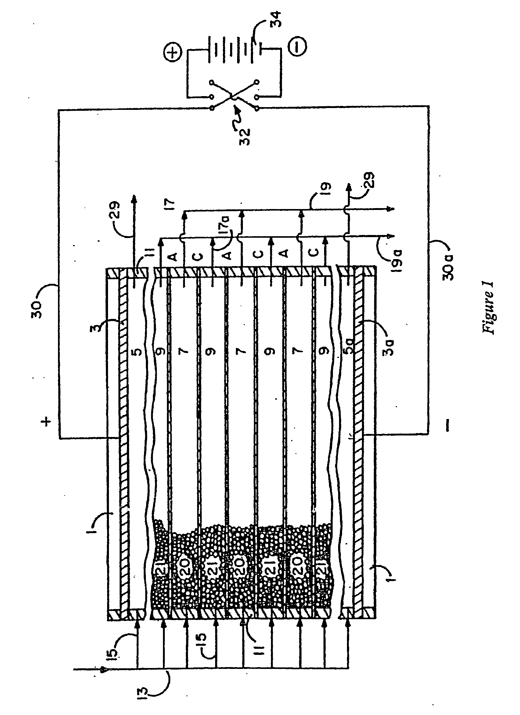
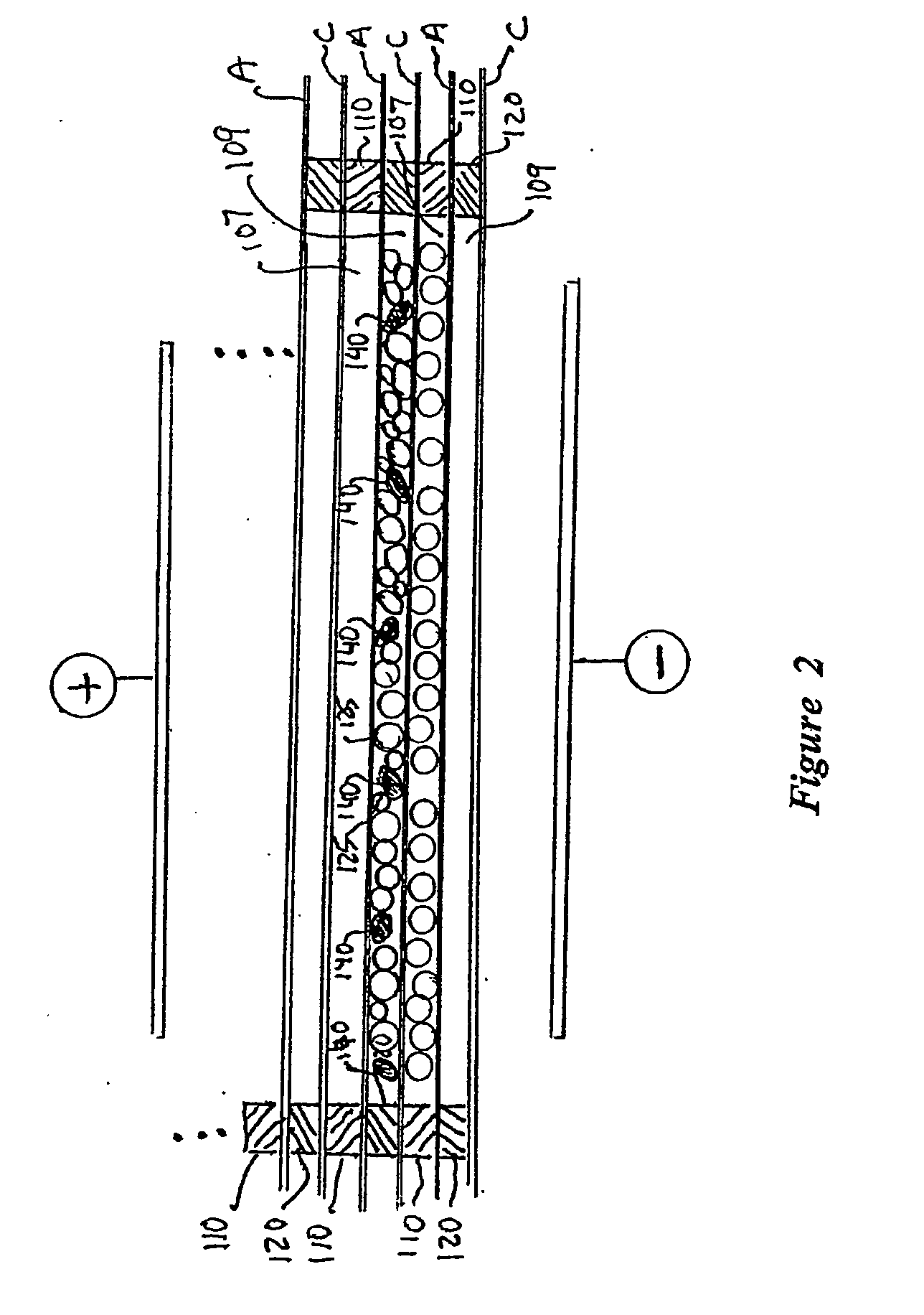
[0089] Two IONICS 4″×20″ EDI stacks of eight cell pairs were assembled. One had conventional 120-mil thick dilute cell spacers and the other had dilute cell spacers thirty mils (0.75 mm) thick, effective to define a bi-layer dilute chamber. Layers of beads were distributed and fixed onto the membanes in the central region of the 30 mil spacers by sieving onto a wetted membrane that was covered with a nine strand per inch screen. The screen maintained the deposited beads in position. Both stacks employed the manufacturer's customary anion exchange and cation exchange membranes, and the customary anion exchange and cation exchange resin beads. The two stacks were both tested at a flow rate 0.32 GPM, with a feed water having conductivity of 23 μm / cm and silica loading of 650-695 ppb.

[0090] Table 1 shows the test results. The sparse bead EDI device performance is characterized by higher product resistance, better silica rejection and lower overall stack electrical resistance. The diffe...

example 2

[0091] The surface specific resistance (in Ohms * sq. cm) of one EDI cell having a conventional cation exchange membrane was measured in two series of experiments. In the first series of experiments a conventional screen spacer #3792 (Naltex R) was used with no resin filling. In another series of experiments the same screen was covered by 60 mg / sq. cm of cation exchange resin 650C which was UPW fixed on the screen with Glycerol. A probe current range of 1-5 mA / sq. cm DC was used to carry out surface specific resistance measurements with Na2SO4 test solution having conductivities between 200 and 600 μSm*cm. Cell thickness was 1.60 mm. Results are shown in Table 2.

TABLE 2EDI cell surface specific resistance (Ohm * sq. cm)Na2SO4Cell without cationCell with cationsolution conduct.exchange resin,exchange resin,μSm * cmOhm * sq. cmOhm * sq. cm2001500110400118084600102583

[0092] The data in the Table show that distributing 60 mg / sq. cm of cation exchange resin 650C-UPW in the spacer fixed...

example 3

[0093] A three cell 4″×20″ sparsely filled cell EDI stack (active area 170 sq. cm) with two electrode cells and one dilute cell was built using customary anion exchange and cation exchange membranes of Ionics, Incorporated EDI constructions. The dilute cell was formed with a screen spacer unit formed of 20 mil PE or EVA film melt bonded with a #4610-Naltex R (20 mil) screen. Then, one side of the screen was covered by 4.7 g of dry Dowex Monosphere 550A UPW (OH) anion exchange beads and the other was covered by 0.85 g of a mixture of Dowex Monosphere 650C UPW (H): Dowex Monosphere 500C NG (H)=1:1. The dilute cell contained 85% of 550A UPW (OH), 7.5% of 650C UPW (H) and 7.5% of 500C NG (H). All IX resins were fixed on the spacer by Glycerin. Each electrode cell had a Ti / Pt electrode and was formed by one 4×20 inch regular IONICS EDI electrode spacer (net #3957C, thickness −0.70 mm) covered by 3.00 g of dry 650C UPW fixed by Glycerin.

[0094] The current was 1010 mA, inlet water specifi...


PUM

PropertyMeasurementUnit
thickaaaaaaaaaa
mean diameteraaaaaaaaaa

Abstract

An electrodeionization, (EDI) apparatus has flow cells with a sparse distribution of ion exchange (IX) material or beads. The beads extend between membranes defining opposed walls of the cell to separate and support the membranes, and form a layer substantially free of bead-to-bead dead-end reverse junctions. The beads enhance capture of ions from surrounding fluid in dilute cells, and do not throw salt when operating current is increased. In concentrating cells, the sparse bead filling provides a stable low impedance bridge to enhanced power utilization in the stack. A monotype sparse filling may be used in concentrate cells, while mixed, layered, striped, graded or other beads may be employed in dilute cells. Ion conduction paths are no more than a few grains long and the lower packing density permits effective fluid flow. A flow cell thickness may be below one millimeter, and the beads may be discretely spaced, form a mixed or patterned monolayer, or form an ordered bilayer, and a mesh having a lattice spacing comparable to or of the same order of magnitude as resin grain size, may provide a distributed open support that assures a stable distribution of the sparse filling, and over time maintains the initial balance of uniform conductivity and good through-flow. The cells or low thickness and this resin layers relax stack size and power supply constraints, while providing treatment efficiencies and process stability. Reduced ion migration distances enhance the ion removal rate without reducing the product flow rate. The sparse resin bed may be layered, graded along the length of the path, striped or otherwise patterned. Inter-grain ion hopping is reduced or eliminated, thus avoiding the occurrence of salt-throwing which occurs at reverse bead junctions of prior art constructions. Conductivity of concentrate cells is increased, permitting more compact device construction, allowing increases in stack cell number, and providing more efficient electrical operation without ion additions. Finally, ion storage within beads is greatly reduces, eliminating the potential for contamination during reversal operation. Various methods of forming sparse beds and assembling the stacks are disclosed.

Description

BACKGROUND AND RELATED ART [0001] The present invention relates to electrodialysis, and particularly to apparatus and processes for filled-cell electrodialysis, also called electrodeionization, filled cell EDI, or simply EDI. In EDI, a plurality of fluid flow cells, typically long flat chambers, are defined between respective pairs of selectively ion-permeable membranes. These cells, include “dilute” cells through which a feed steam flows, alternating with “concentrate” cells positioned adjacent to the dilute cells for receiving ions removed from the feed stream. All cells are all arranged between a pair of electrodes, which are located at opposite ends of the stack or sequence of layers, and which provide an electric field oriented across the direction (and the planes) of the fluid flows. A packing of ion exchange material, typically ion exchange resin beads, is placed in the dilute cells to more effectively strip ions from the fluid as the fluid flows through the dilute cells, and...

Claims


Application Information

Patent Timeline
Patent Type & Authority Applications(United States)
IPC IPC(8): C02F1/42B01D71/82B01D61/48B01J47/08C02F1/469C25B9/00C25B13/02
CPCB01D61/48B01D2313/30C02F2303/16C02F1/4695C02F2201/46105B01J47/08C02F2201/46115C02F1/461C25B9/23
Inventor GREBENYUK, VLADIMIRCARSON, WILLIAM M.GREBENYUK, OLEGSIMS, KEITH J.MACDONALD, RUSSELL J.
Owner IONICS INC
Why Eureka
Try Eureka