Crystal growth apparatus and manufacturing method of group III nitride crystal

a technology of nitride crystal and crystal growth apparatus, which is applied in the direction of crystal growth process, polycrystalline material growth, condensed vapor growth, etc., can solve the problems of retarded reduced nitrogen dissolved in the melt mixture, and increased nitrogen supersaturation. , to achieve the effect of facilitating crystal growth of the group iii nitride crystal from the seed crystal, increasing the degree o

Active Publication Date: 2007-04-19
SUMITOMO CHEM CO LTD +1
View PDF31 Cites 54 Cited by
  • Summary
  • Abstract
  • Description
  • Claims
  • Application Information

AI Technical Summary

Benefits of technology

[0160] Thus, according to the present invention, it becomes possible to manufacture a group III nitride crystal of large size.
[0161] Further, in a preferred embodiment, the crystal growth of the group III nitride crystal is achieved by setting the temperature of the seed crystal to a temperature lower than the temperature of the me...

Problems solved by technology

However, with such a conventional method that causes growth of a group III nitride crystal by causing to react the melt mixture of alkali metal and group III metal with a nitrogen gas, there has been a problem in that the alkali metal causes evaporation from the melt mixture and escapes to the outside in the form of vapor.
As a result, the amount of nitrogen dissolved into the melt mixture is decreased and there arises a problem...

Method used


Image

  • Crystal growth apparatus and manufacturing method of group III nitride crystal
  • Crystal growth apparatus and manufacturing method of group III nitride crystal
  • Crystal growth apparatus and manufacturing method of group III nitride crystal

Examples


embodiment 1

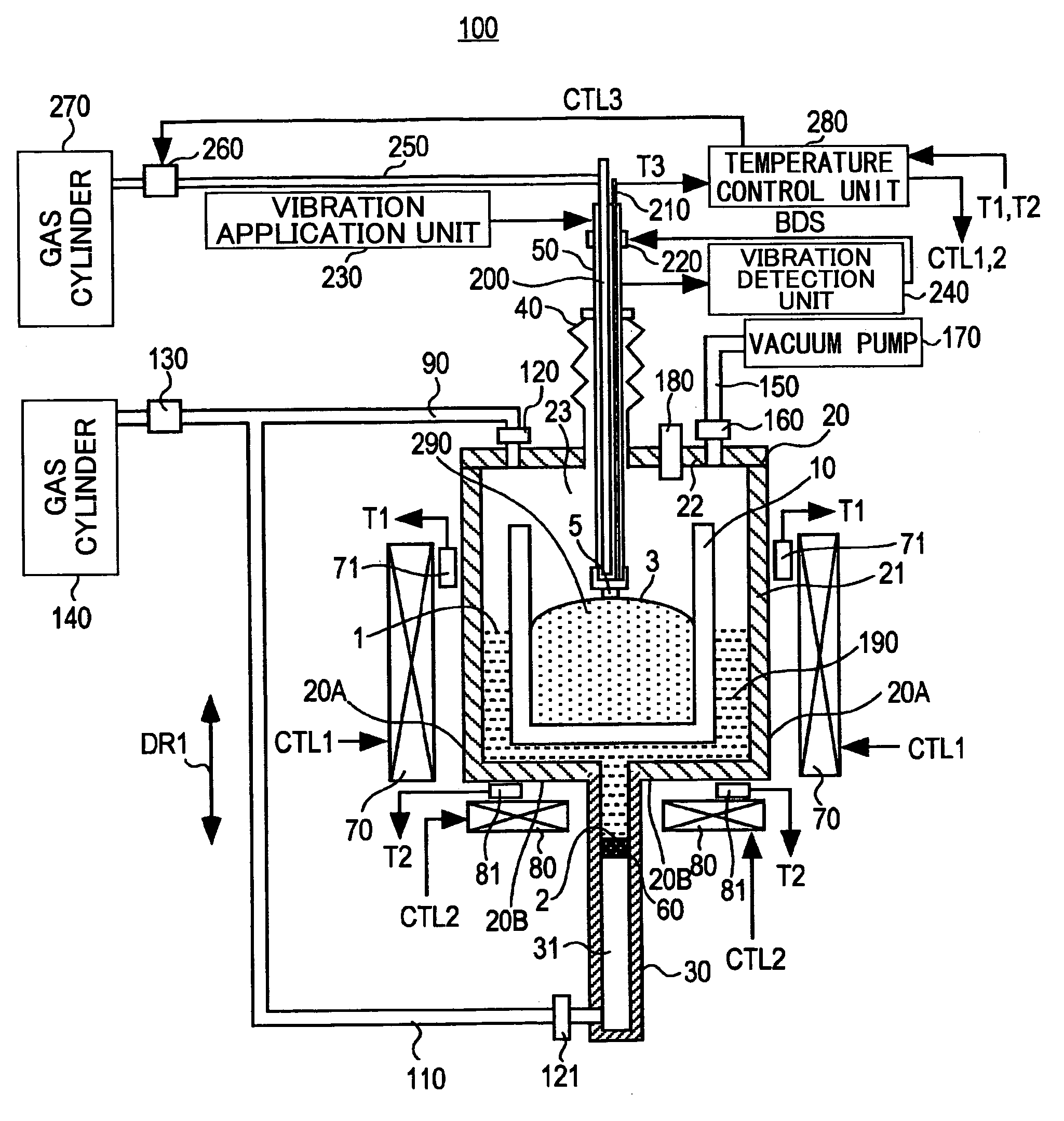
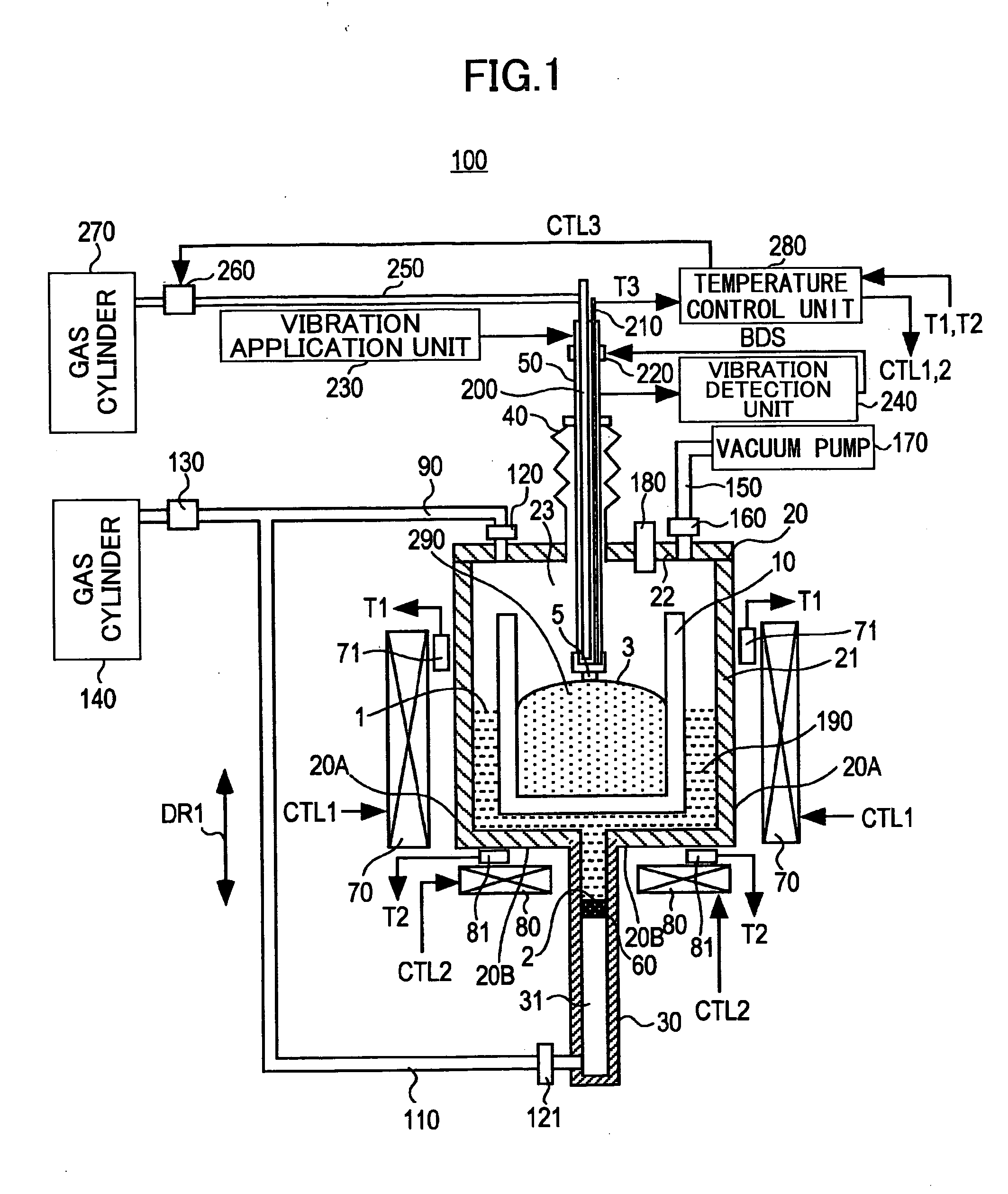
[0313]FIG. 1 is a schematic cross-sectional diagram showing the construction of a crystal growth apparatus according to Embodiment 1 of the present invention.

[0314] Referring to FIG. 1, a crystal growth apparatus 100 according to Embodiment 1 of the present invention comprises: a crucible 10; a reaction vessel 20; conduits 30 and 200; a bellows 40; a support unit 50; a stopper / inlet plug 60; heating units 70 and 80; temperature sensors 71 and 81; gas supply lines 90, 110, 250, valves 120, 121, 160; a pressure regulator 130; gas cylinders 140 and 270; an evacuation line 150; a vacuum pump 170; a pressure sensor 180; a metal melt 190; a thermocouple 210; an up / down mechanism 220; a vibration applying unit 230; a vibration detection unit 240; a flow meter 260; and a temperature control unit 280.

[0315] The crucible 10 has a generally cylindrical form and is formed of boron nitride (BN). The reaction vessel 20 is disposed around the crucible with a predetermined separation from the cru...

embodiment 2

[0471]FIG. 16 is a schematic cross-sectional diagram showing the construction of a crystal growth apparatus according to Embodiment 2 of the present invention.

[0472] Referring to FIG. 16, the crystal growth apparatus 100A of Embodiment 2 has a construction similar to that of the crystal growth apparatus 100 except that the conduit 30 of the crystal growth apparatus 100 shown in FIG. 1 is changed to conduits 300 and 310, the metal melt 190 is changed to a metal melt 330, and heating units 320 and 340 are added.

[0473] The conduit 300 has an end connected to the reaction vessel 20. The conduit 310 has an end connected to the other end of the conduit 300 and the other end connected to the gas supply line 110. With the crystal growth apparatus 10A, the stopper / inlet plug 60 is disposed inside the conduit 310. Thereby, the metal melt 330 is held inside the conduit 310 by the stopper / inlet plug 60.

[0474] The heating unit 320 is provided so as to face the conduit 3000.

[0475] In the crys...

embodiment 3

[0554]FIG. 22 is a schematic cross-sectional diagram showing the construction of a crystal growth apparatus according to Embodiment 3 of the present invention.

[0555] Referring to FIG. 22, the crystal growth apparatus 1100 according to Example 3 of the present invention includes: a crucible 1010; a reaction vessel 1020; a conduit 1030; a bellow 1040; a stopper / inlet plug 1050; heaters 1060 and 1070; a gas supply liens 1090 and 1110; valves 1120, 1121 and 1160; a pressure regulator 1130; a gas cylinder 1140; an evacuation line 1150; a vacuum pump 1170; a pressure sensor 1180; a metal melt 1190; a support unit 1210; an up / down mechanism 1220; a vibration application unit 1230; a vibration detection unit 1240; a filler 1250; and a metal member 1260.

[0556] The crucible 10 has a generally cylindrical form and is formed of boron nitride (BN). The reaction vessel 1020 is disposed around the crucible with a predetermined separation from the crucible 1010. Further, the reaction vessel 1020 ...


PUM


Abstract

A crystal growth apparatus comprises a reaction vessel holding a melt mixture containing an alkali metal and a group III metal, a gas supplying apparatus supplying a nitrogen source gas to a vessel space exposed to the melt mixture inside the reaction vessel, a heating unit heating the melt mixture to a crystal growth temperature, and a support unit supporting a seed crystal of a group III nitride crystal inside the melt mixture.

Description

BACKGROUND OF THE INVENTION [0001] The present invention relates to a crystal growth apparatus growing a group III nitride crystal and a method of manufacturing a group III nitride crystal. Particularly, the present invention relates to a manufacturing method of a GaN crystal. [0002] These days, most of the InGaAlN (a group III nitride semiconductor) devices used for ultraviolet, purple, blue and green optical sources are formed on a substrate of sapphire or silicon carbide (SiC) by conducting thereon an MOCVD process (metal-organic chemical vapor deposition process) or MBE process (molecular beam epitaxy process). [0003] In the case sapphire or silicon carbide is used for the substrate, however, there are formed a large number of crystal defects in the group III nitride semiconductor layers grown thereon in view of the fact that there exists a large difference in the thermal expansion coefficient and in the lattice constant between the substrate and the group III nitride semiconduc...

Claims


Application Information

Patent Timeline
IPC IPC(8): C30B11/00C30B9/00C30B17/00C30B21/02C30B28/06
CPCC30B9/00Y10T117/1092C30B29/40C30B17/00C30B9/10C30B19/02C30B19/062C30B19/106C30B29/406C30B9/12C30B29/403
Inventor SARAYAMA, SEIJIIWATA, HIROKAZUFUSE, AKIHIRO
Owner SUMITOMO CHEM CO LTD
Why Eureka
Try Eureka