R-t-b system permanent magnet

a permanent magnet and rtb technology, applied in the field of improving the corrosion resistance of an can solve the problems of poor degraded magnetic properties, and so as to improve the corrosion resistance of rtb system permanent magnets with an overcoat formed thereon

Active Publication Date: 2007-05-10
TDK CORPARATION
View PDF6 Cites 20 Cited by
  • Summary
  • Abstract
  • Description
  • Claims
  • Application Information

AI Technical Summary

Benefits of technology

[0018] Embodiment 1 may comprise an embodiment (embodiment 1-1) in which the hydrogen-rich layer has a hydrogen concentration of 1000 ppm or more, and another embodiment (embodiment 1-2) in which the hydrogen-rich layer has a hydrogen concentration of 300 to 1000 ppm. According to embodiment 1-1, the corrosion resistance of the R-T-B system permanent magnet with an overcoat formed thereon can be improved without degrading the magnetic properties thereof. Also, according to embodiment 1-2, partial collapse of the surface of the magnet body, occurring when an overcoat is formed, can be suppressed.

Problems solved by technology

Even the R-T-B system permanent magnets having excellent magnetic properties involve some technical problems to be solved.
One of such problems is corrosion resistance.
More specifically, the R-T-B system permanent magnets are poor in corrosion resistance because their main constituent elements, namely, R and Fe, are elements susceptible to oxidation.
However, reduction of the content of R degrades the magnetic properties.
An R-T-B system permanent magnet is generally produced by means of a powder metallurgy method in which a fine alloy powder of a few microns in particle size is compacted and sintered; such an alloy powder contains a considerable amount of chemically extremely active R, and hence the powder undergoes oxidation during the production steps to result in reduction of the amount of R effective in attaining magnetic properties; and thus, it becomes impossible to overlook the degradation of the magnetic properties, in particular, the degradation of the coercive force.
When the Ni plating or Ni alloy plating method is applied to the R-T-B system permanent magnet which has a high hydrogen absorptivity and has a property that hydrogen absorptivity thereof embrittles itself, the hydrogen generated during plating is absorbed inside the R-T-B system permanent magnet, so that brittle fracture and plating exfoliation are caused on the plating interface and the corrosion resistance can no longer be maintained.
According to Patent Document 3, the heating under vacuum at temperatures of 600° C. or higher and lower than 800° C. reduces the amount of hydrogen, but tends to degrade the magnetic properties and brings about a fear of degrading the plating coat.
The degradation of the plating coat causes the degradation of the corrosion resistance, and hence will be incompatible with the primary purpose of the plating coat.
According to Patent Document 5, it is necessary electrolytic plating be applied with a low current density and a low voltage; this may bring about a fear of considerable degradation of the production efficiency and no account is taken for the corrosion resistance of the overcoat formed by electrolytic plating.
However, needless to say, the dimensions concerned are significantly affected by the dimensions of the magnet body.
As for the magnet body, it is subjected to barrel polishing treatment before plating so as to round the edge portions thereof which otherwise tend to undergo formation of humps of the plating coat; however, there is a problem such that the surface of the magnet body is partially collapsed (detachment of grains) when thereafter undergoing acid etching and plating coat formation, giving a factor to degrade the dimensional precision of the surface, in particular, the edge portions.

Method used


Image

  • R-t-b system permanent magnet
  • R-t-b system permanent magnet
  • R-t-b system permanent magnet

Examples


example 1-1-1

[0084] A thin strip alloy having a predetermined composition was prepared by means of the strip casting method. The thin strip alloy was made to absorb hydrogen at room temperature, and thereafter, the absorbed hydrogen was released by raising the temperature up to approximately 400 to 700° C. in an atmosphere of Ar to yield a coarse powder.

[0085] The coarse powder was pulverized by use of a jet mill. The pulverizing was carried out in such a way that the inside of the jet mill was purged with N2 gas and thereafter a high pressure N2 gas flow was used. The content of O2 in the high pressure N2 gas was at a level to be regarded as substantially null. The mean particle size of the obtained fine powder was 4.0 μm. It is to be noted that zinc stearate was added before pulverizing as a milling aid in a content of 0.01 to 0.10 wt % and the content of the residual carbon in the sintered body was controlled.

[0086] The obtained fine powder was compacted in a magnetic field of 1200 kA / m (15...

example 1-1-2

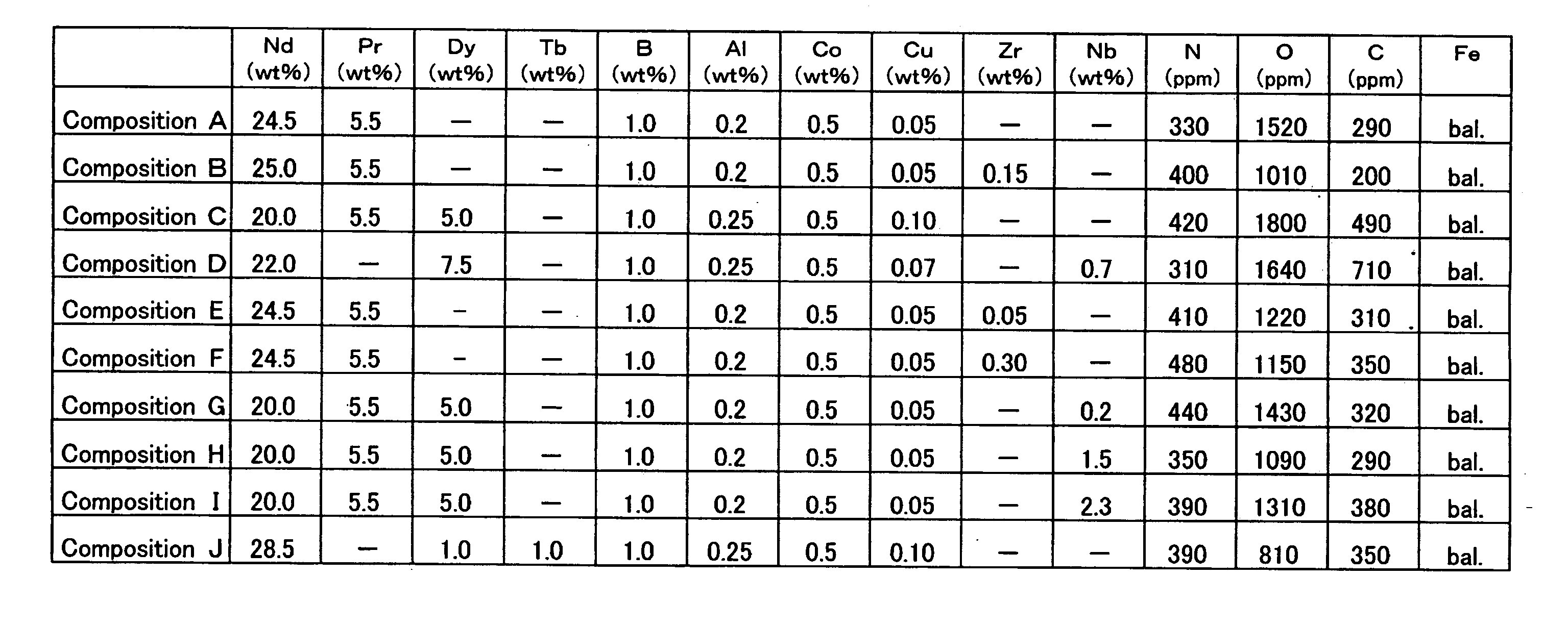
[0093] In the same manner as in Example 1-1-1 (except that oleic acid amide was added as a milling aid in a content of 0.05 to 0.20 wt % before pulverizing), the sintered magnets having the compositions shown in FIG. 6 were prepared, and the corrosion resistance was evaluated and the magnetic properties were measured for each of the sintered magnets. Also, in the same manner as in Example 1-1-1, the sum of the areas of the R2Fe14B grains of 10 μm or less in grain size and the sum of the areas of the R2Fe14B grains of 20 μm or more in grain size in relation to the total area of the main phase were measured for each of the sintered magnets. The results thus obtained are shown in FIG. 7.

[0094] As shown in FIG. 7, sample No. 19 having a content of N as low as 100 ppm was worse in corrosion resistance than sample No. 18; and sample No. 20 having a content of N as large as 1800 ppm was low in coercive force. Thus, the content of N needs to be controlled to fall within a predetermined ran...

example 1-2

[0098] A thin strip alloy having a predetermined composition was prepared by means of the strip casting method. The thin strip alloy was made to absorb hydrogen at room temperature, and thereafter, the absorbed hydrogen was released by raising the temperature up to approximately 400 to 700° C. in an atmosphere of Ar to yield a coarse powder.

[0099] The coarse powder was pulverized by use of a jet mill. The pulverizing was carried out in such a way that the inside of the jet mill was purged with N2 gas and thereafter a high pressure N2 gas flow was used. The mean particle size of the obtained fine powder was 4.0 μm. It is to be noted that zinc stearate was added before pulverizing as a milling aid in a content of 0.05 wt %.

[0100] The obtained fine powder was compacted in a magnetic field of 1200 kA / m (15 kOe) under a pressure of 98 MPa (1.0 ton / cm2) to yield a compacted body. The compacted body was sintered under vacuum at 1030° C. for 4 hours, and thereafter quenched. The obtained ...


PUM

PropertyMeasurementUnit
thicknessaaaaaaaaaa
grain sizeaaaaaaaaaa

Abstract

An R-T-B system permanent magnet 1 comprises a magnet body 2 comprising a sintered body comprising at least a main phase comprising R2T14B grains (wherein R represents one or more rare earth elements, and T represents one or more transition metal elements including Fe or Fe and Co essentially) and a grain boundary phase containing R in a larger amount than the main phase, the magnet body 2 having a 300 μm or less thick (not inclusive of zero thick) hydrogen-rich layer 21 having a hydrogen concentration of 300 ppm or more formed in the surface layer portion, and an overcoat 3 covering the surface of the magnet body 2 can improve the corrosion resistance of the R-T-B system permanent magnet 1 with an overcoat 3 formed thereon without degrading the magnetic properties thereof. The present invention can be applied to formation of the overcoat 3 by electrolytic plating, can fully ensure the corrosion resistance as a primary target of the overcoat 3 formation without substantially degrading the production efficiency, and can provide the R-T-B system permanent magnet 1 with a high dimensional precision by suppressing the partial collapse (detachment of grains) of the surface thereof.

Description

TECHNICAL FIELD [0001] The present invention relates to the improvement of the corrosion resistance of an R-T-B system permanent magnet. BACKGROUND ART [0002] R-T-B system permanent magnets (wherein R represents one or more rare earth elements and T represents Fe or Fe and Co) in each of which the main phase thereof comprises grains composed of an R2T14B type intermetallic compound (wherein referred to as R2T14B grains in the present invention) have been used in various electric devices and machines because the R-T-B system permanent magnets are each excellent in magnetic properties and a main component of each thereof, Nd, is abundant as a natural resource and relatively inexpensive. [0003] Even the R-T-B system permanent magnets having excellent magnetic properties involve some technical problems to be solved. One of such problems is corrosion resistance. More specifically, the R-T-B system permanent magnets are poor in corrosion resistance because their main constituent elements,...

Claims


Application Information

Patent Timeline
Patent Type & Authority Applications(United States)
IPC IPC(8): H01F1/057H01F41/02
CPCC22C38/005H01F1/0577Y10T428/12465H01F41/26H01F41/026
Inventor HIDAKA, TETSUYAOKADA, HIRONARISAKAMOTO, KAZUYASAKAMOTO, TAKESHINAKAYAMA, YASUYUKIYAMAMOTO, TOMOMI
Owner TDK CORPARATION
Why Eureka
Try Eureka