Work device comprising bordered work zones, on-chip laboratory and microsystem

Inactive Publication Date: 2007-05-10
COMMISSARIAT A LENERGIE ATOMIQUE ET AUX ENERGIES ALTERNATIVES +1
View PDF11 Cites 13 Cited by
  • Summary
  • Abstract
  • Description
  • Claims
  • Application Information

AI Technical Summary

Benefits of technology

[0051] The type of the surface, outside of the depressions, and also advantageously inside the depressions, is an important parameter for the good overall functioning of the device of the present invention. The treatment of the substrate surface to make it substantially non-wetting can be effected before or after the formation of the depressions in order to modify the affinity of the zones on the substrate: between the depressions and, advantageously at their centre. Thus, the removal by suction of the liquid of interest is facilitated by a weak affinity between the liquid of interest and the surface between the depressions. Furthermore, the centre of the depressions may advantageously have a good affinity for the liquid phase to facilitate the capture of a drop of liquid of interest in the depressions.
[0052] Quite unexpectedly, the inventors observed that when the entire substrate surface, that is, the centre of the depressions formed by the borders and the surface between the depressions, has a poor affinity for the liquid of interest, particularly if it is substantially non-wetting

Problems solved by technology

These systems lead to the formation of drops and of matrices with a high density of spots or drops on a surface.
However, besides the drop dispensing system, all these techniques require a device for the accurate movement and alignment of this system, as well as a liquid feed device.
This apparatus is very costly.
Furthermore, the maximum density-of the drop matrices which can be formed is limited by a combination between the size of the drops dispensed and the minimum inter-spot spacing of the dispensing system.
However, the edges of these depressions leave no ph

Method used


Image

  • Work device comprising bordered work zones, on-chip laboratory and microsystem
  • Work device comprising bordered work zones, on-chip laboratory and microsystem
  • Work device comprising bordered work zones, on-chip laboratory and microsystem

Examples


Example

Example 1

Production of Capture Zones Formed from Borders

[0123] A photolithography step is carried out on a fresh silicon wafer with a Clariant AZ4562 (trade name) thick photoresist as follows: [0124] deposition of an adhesion promoter, which is hexamethylenedisilazane here, in an oven at 120° C., [0125] spin-coating of resin at 1000 rpm for 30 seconds with an acceleration of 200 rpm / s, [0126] annealing on hotplate at 115° C. for 2 minutes, [0127] insolation on Karl Süss MA750 (trade name) exposure machine for 50 seconds in batch mode (5×10 seconds with 5 seconds pause) through a mask, [0128] development in a Shipley MF319 (trade name) solution diluted in proportions of 1:3 with deionized water, [0129] cleaning with deionized water and drying under nitrogen stream, [0130] annealing on a hotplate at 115° C. for 3 minutes, then at 150° C. for 1 minute, [0131] thickness measurement: 13 μm.

[0132] On the mask used for insolation, all the motifs represent rings of which the walls have a...

Example

Example 2

Production of the Box

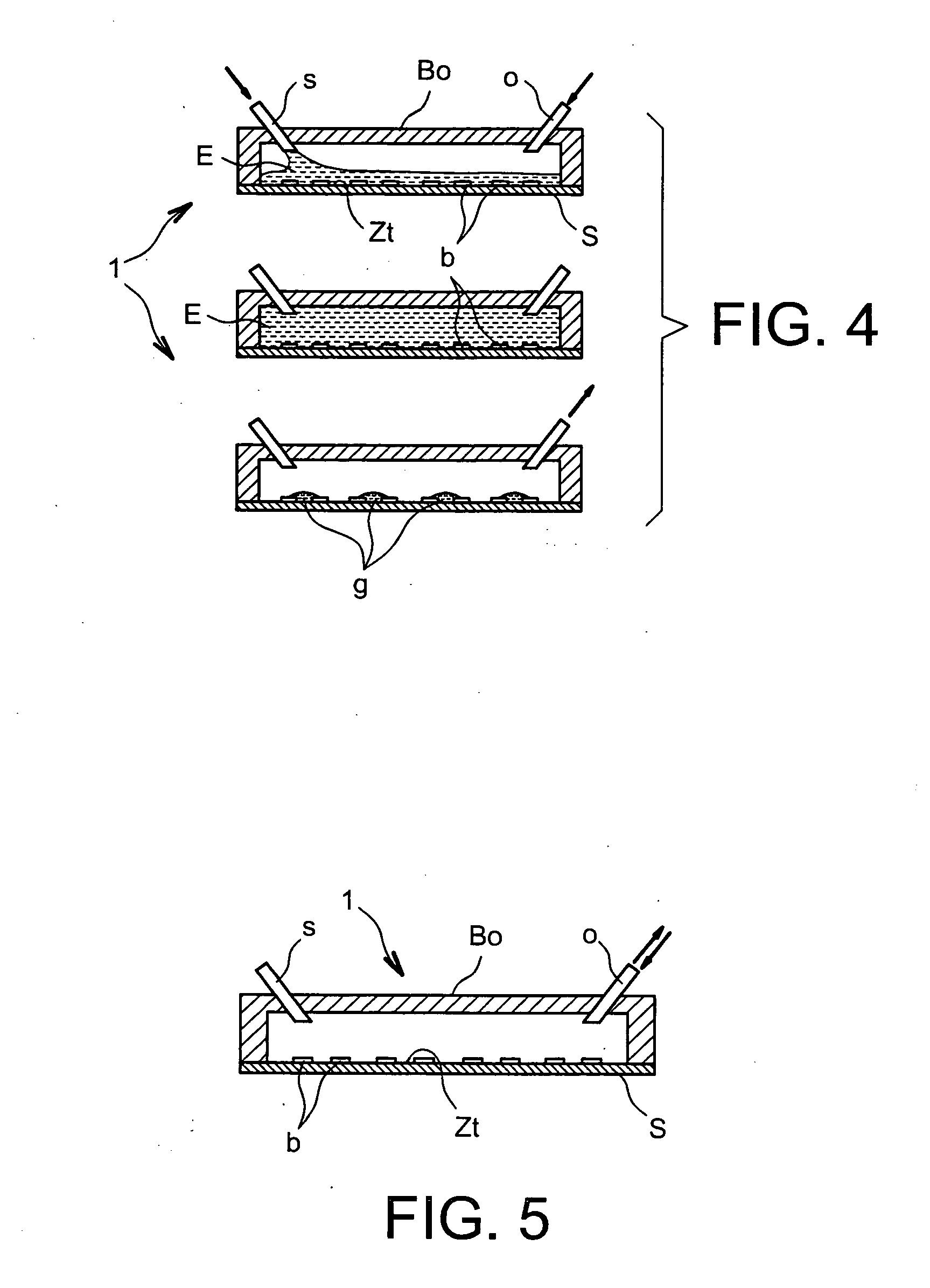
[0134] A hollow cover of polydimethylsiloxane (PDMS) is produced by moulding on a glass mould with a square pattern and an oventhickness of 1 mm. On a plane device like those obtained with the preceding example, this hollow cover is fixed hermetically by bonding with crosslinking adhesive by irradiation with ultraviolet radiation (VITRALIT 6181). The connections for the fluid inlets and outlets are made by drilling the cover with small-diameter needles. The inlet needle is connected to fluid transport tubes and to a syringe filled with liquid of interest. The final assembly is tested for leaks, in the knowledge that the liquid must only pass through the connections provided for this purpose.

[0135]FIG. 4 is a schematic representation of the box obtained in this example. Other arrangements of the inlet and outlet connections (o, s) for introducing and extracting a liquid of interest can easily be obtained according to this example, and FIG. 9 schematic...

Example

Example 3

Capture of Deionized Water on a Silicon Surface with Native Oxide

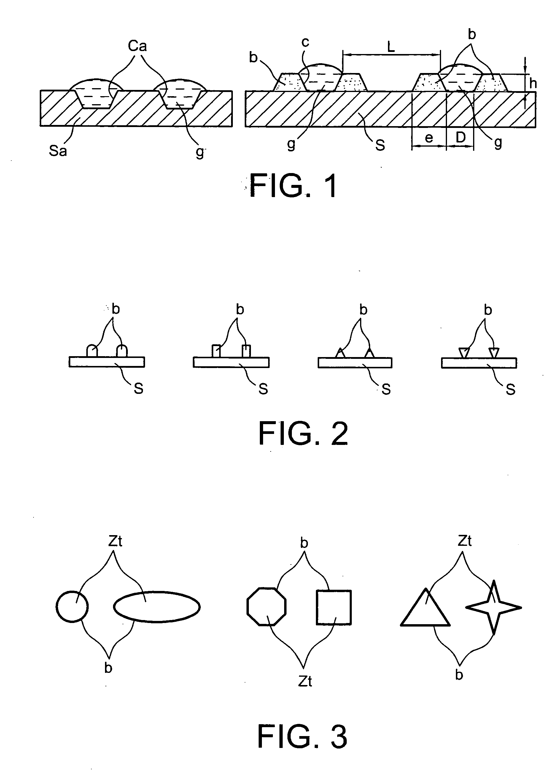
[0137] Various types of features forming borders according to the invention, shown in FIGS. 1 to 3 appended hereto, and obtained by the method described in example 1, are tested with deionized water (DW).

[0138] For this purpose, covers with a fluid stream about 1 mm thick created thanks to a work box according to the invention, produced according to example 2 (FIG. 4 appendedhereto) are used for the injection and extraction of DW, via plastic tubes.

[0139] The initial surface, consisting of silicon with a coat of native oxide, was not treated and the contact angle was close to 68° with the DW.

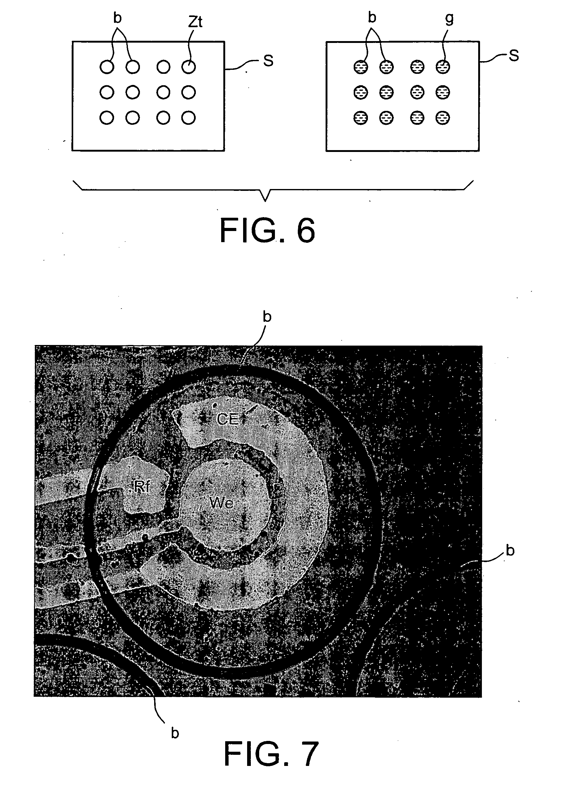
[0140] As shown in FIG. 6 appended hereto, to the right, the DW remains retained in the depressions formed by the border (b), on the work zone (Zt), in the form of drops (g) after removal of the liquid of interest by suction.

[0141] Various methods for filling the box with the liquid of interest were tested: with the ...


PUM


Abstract

The present invention relates to a work device (1) comprising work zones. It can be used to obtain a matrix of drops on a surface, using a liquid of interest (E). It comprises a work box (Bo) provided with means (o, s) for introducing and extracting the liquid respectively into and from the box; a substrate (S) comprising an active surface that is substantially non-wetting for said liquid of interest contained in said box; distinct work zones (Zt) formed on said active surface and each surrounded by a border (b) formed on said active surface, the borders not touching one another and having no common edge and having a geometry such that when the liquid of interest is extracted from the box, a drop (g) of the liquid of interest remains imprisoned by each border and in contact with the work zone that it surrounds.

Description

[0001] The instant application claims the priority of the French patent application filed on Oct. 31, 2003 under number 03 50762, which is incorporated herein by reference. TECHNICAL FIELD OF THE INVENTION [0002] The present invention relates to a work device comprising bordered work zones, to an on-chip laboratory and to a microsystem comprising this device, particularly a biological chip. The present invention further relates to a method for producing a device of the invention. [0003] The present invention makes it possible to obtain a high-density matrix of drops localized on a surface, from a liquid of interest. It enables the easy transition from a closed fluid chamber, called a work box, and filled with a liquid of interest, to a matrix of drops, or microvolumes, perfectly localized on a surface placed in said chamber, when the liquid of interest is removed from said fluid chamber. [0004] The term matrix of drops means a predefined arrangement of said drops, without requiring ...

Claims


Application Information

Patent Timeline
IPC IPC(8): C12M1/34H01L21/00B01J19/00B01L3/00C40B40/06C40B40/10C40B60/14
CPCB01J19/0046B01J2219/00317B01J2219/00585B01J2219/00596B01J2219/0065B01J2219/00653B01J2219/00659B01J2219/00677B01J2219/00722B01J2219/00725B01J2219/00743B01L3/5027B01L3/5085B01L3/5088B01L2300/0636B01L2300/0645B01L2300/0816B01L2300/0819B01L2300/0877B01L2300/089B01L2400/0487C40B40/06C40B40/10C40B60/14
Inventor DELATTRE, CYRILMARCHAND, GILLESPOUTEAU, PATRICKGINOT, FREDERIC
Owner COMMISSARIAT A LENERGIE ATOMIQUE ET AUX ENERGIES ALTERNATIVES
Why Eureka
Try Eureka