Method of Producing Metal Oxide Film

a metal oxide film and metal oxide technology, applied in the field of metal oxide film production, can solve the problems of poor shape-following properties, increased costs and complex operability, and difficulty in forming an even metal oxide film on a substrate with a structural par

Inactive Publication Date: 2007-12-27
DAI NIPPON PRINTING CO LTD
View PDF11 Cites 20 Cited by
  • Summary
  • Abstract
  • Description
  • Claims
  • Application Information

AI Technical Summary

Benefits of technology

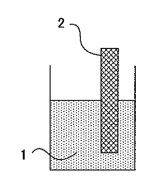
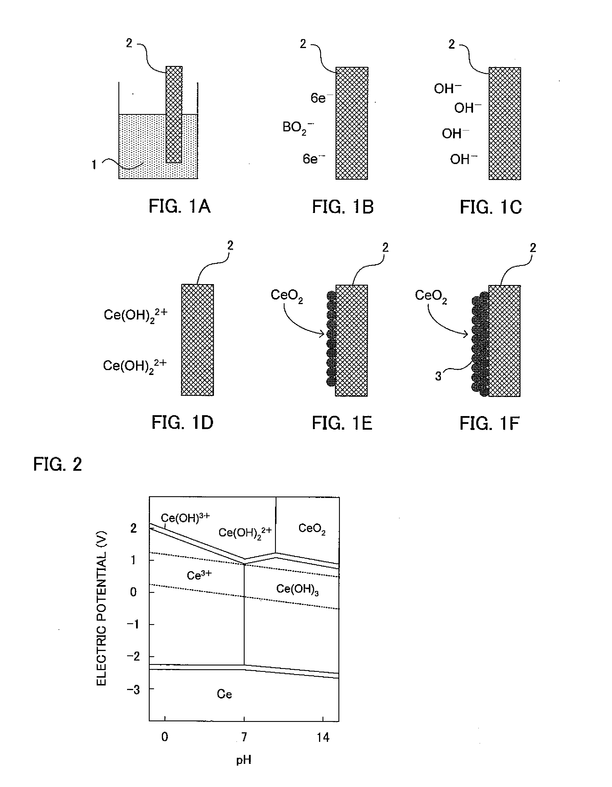
[0004] Against such problems, suggested is a soft solution process of forming a metal oxide film directly from a solution onto a substrate (Non-Patent Document 1). Since neither firing nor any high-vacuum state is necessary in this soft solution process, the above-mentioned problems such as the grow in machine size can be solved. Furthermore, a substrate is brought into contact with a metal oxide film-forming solution; therefore, even if the substrate is a substrate having a complicated structural part, the solution can be caused to invade the inside of the structural part easily so that an even metal oxide film is obtained.
[0005] As an example of an attempt to use this soft solution process, Patent Document 1 discloses a method of causing a reaction solution which contains constituting elements of a thin film to be formed to flow, at a predetermined flow rate, between an anode electrode and a cathode electrode to which a predetermined voltage is applied, thereby forming a thin film. In Patent Document 1, the reaction solution contains an oxidizing agent but contains no reducing agent. Furthermore, the substrate is limited to electroconductive bodies and the granularity is rough in terms of the film quality of the resultant thin film.
[0006] Further for example, Patent Documents 2 and 3 each disclose a method of immersing a substrate subjected to catalytic treatment with an Ag catalyst or a Pd catalyst into a zinc oxide deposition solution so as to form a zinc oxide film by electroless deposition. According to these Patent Documents, a reducing agent such as dimethylamine borane is used, but the catalytic treatment of the substrate is an essential constituting element; thus, the method is not a method for forming a metal oxide film directly onto a surface of a substrate. Furthermore, in accordance with the usage of the metal oxide film, it is supposed that the metal used in the catalyst may not preferable in some cases. Moreover, there arises a problem that the process becomes complicated since the catalytic treatment is conducted.
[0007] In light of the above-mentioned problems, the present invention has been made. A main object is to provide a method of producing a metal oxide film in which the metal oxide film is formed directly onto a surface of a substrate without subjecting the substrate surface to catalytic treatment, and the method which enables to make the obtained metal oxide film even through a simple process even if the substrate has a complicated structural part.

Problems solved by technology

Thus, the machines required become large-sized to lead to problems such as the increase in costs and complex operability.
A different problem in the methods for producing a metal oxide film is that it is difficult to form an even metal oxide film onto a substrate that has a structural part.
For example, in sputtering, the shape-following properties are poor because of its operation mechanism.
In printing, it is difficult to form a film onto a structural part which is smaller than fine ceramic particles contained in ink.
However, it is difficult to form an even metal oxide film onto a complicated structural part.
Furthermore, the substrate is limited to electroconductive bodies and the granularity is rough in terms of the film quality of the resultant thin film.
According to these Patent Documents, a reducing agent such as dimethylamine borane is used, but the catalytic treatment of the substrate is an essential constituting element; thus, the method is not a method for forming a metal oxide film directly onto a surface of a substrate.
Furthermore, in accordance with the usage of the metal oxide film, it is supposed that the metal used in the catalyst may not preferable in some cases.
Moreover, there arises a problem that the process becomes complicated since the catalytic treatment is conducted.

Method used


Image

  • Method of Producing Metal Oxide Film
  • Method of Producing Metal Oxide Film
  • Method of Producing Metal Oxide Film

Examples


example 1

Formation of an ITO Film on a Porous Alumina Particle Layer

[0078] A 20 wt % solution of alumina fine particles (manufactured by Micron Co., Ltd., particle diameter: 30 μm) was coated onto a glass substrate by a bar coating manner, and the resultant was fired at a temperature of 500° C. for 2 hours to yield the glass substrate on which a porous alumina particle layer was formed.

[0079] Next, a boron-trimethylamine complex (manufactured by KANTO KAGAKU) as a reducing agent was added to 1000 g of a 0.03 mol / L indium chloride and 0.001 mol / L tin chloride solution in water so as to give a concentration of 0.1 mol / L. Furthermore, 2 g of sodium chlorinate was added as an auxiliary ion source to the solution to yield a metal oxide film-forming solution.

[0080] Next, the substrate obtained by the above-mentioned method was immersed in the above-mentioned solution at a temperature of 70° C. for 12 hours. At this time, the metal oxide film-forming solution was circulated and caused to pass th...

example 2

Formation of a Zirconium Oxide Film on a Copper Substrate Subjected to Microfabrication

[0084] In the present example, a zirconium oxide film was formed on a copper substrate subjected to a microfabrication, and the corrosion resistance thereof was evaluated.

[0085] In the example, a copper (thickness: 0.5 mm) subjected to a microfabrication (holes 1 mm in diameter and 50 μm in depth, and grooves 50 μm in width, 10 mm in length, and 20 μm in depth) by an etching method was firstly prepared as a substrate.

[0086] Next, a boron-dimethylamine complex (model number: 04886-35, manufactured by KANTO KAGAKU) as a reducing agent was added to 1000 g of a 0.03 mol / L oxyzirconium nitrate solution in water to give a concentration of 0.1 mol / L, so as to yield a metal oxide film-forming solution.

[0087] Next, the metal oxide film-forming solution was heated up to a temperature of 70° C., and a Naflon Bubbler (manufactured by AS ONE CORPORATION) was used to generate air bubbles at a constant tempe...

example 3

Formation of a Titanium Oxide Film onto an Acrylic Substrate Subjected to Microfabrication

[0092] An object of the present example was to form a titanium oxide film onto an acrylic substrate that is subjected to a microfabrication, thereby giving hydrophilicity thereto.

[0093] In the example, an acrylic substrate (thickness: 5 μm) subjected to mechanical microfabrication (grooves 500 μm in width, 100 mm in length, and 50 μm in depth) was first prepared as a substrate.

[0094] Next, diisopropoxytitanium bis(ethylacetate) (manufactured by Matsumoto Chemical Industry Co., Ltd.) was dissolved into 1000 g of a mixed solution where water, isopropyl alcohol (IPA), and toluene were adjusted to give a ratio of 4:4:1, so as to give a concentration of 0.1 mol / L. Next, a boron-dimethyl sulfide complex (manufactured by KANTO KAGAKU), as a reducing agent, was added to the solution so as to give a concentration of 0.1 mol / L. Furthermore, 1 g of sodium nitrite was added to the solution to yield a me...


PUM

PropertyMeasurementUnit
thicknessaaaaaaaaaa
thicknessaaaaaaaaaa
wavelengthaaaaaaaaaa

Abstract

A method of producing a metal oxide film in which the metal oxide film is formed directly onto a surface of a substrate without subjecting the substrate surface to catalytic treatment, and the method which enables to make the obtained metal oxide film even through a simple process even if the substrate has a structural part. The metal oxide film is obtained by bringing a surface of a substrate into contact with a metal oxide film-forming solution that has a metal salt or a metal complex dissolved as a metal source, wherein the metal oxide film-forming solution comprises a reducing agent.

Description

TECHNICAL FIELD [0001] The present invention relates to a method of producing a metal oxide film, in which a metal oxide film-forming solution containing a reducing agent is used. BACKGROUND ART [0002] Conventionally, it has been known that metal oxide films exhibit various excellent physical properties. By making good use of this characteristic, the films are used in broad fields of transparent electroconductive films, optical thin films, electrolytes for fuel cells, and the like. Examples of a method of producing such a metal oxide film include a sol-gel method, sputtering, CVD, PVD, and printing. In any one of these methods, firing or a high-vacuum state is required. Thus, the machines required become large-sized to lead to problems such as the increase in costs and complex operability. [0003] A different problem in the methods for producing a metal oxide film is that it is difficult to form an even metal oxide film onto a substrate that has a structural part. For example, in spu...

Claims


Application Information

Patent Timeline
Patent Type & Authority Applications(United States)
IPC IPC(8): C01B13/14C23C18/16
CPCC03C17/25C23C18/16C03C2217/948C03C2218/11C04B35/46C04B35/486C04B35/50C04B35/632C04B2235/3227C04B2235/3229C04B2235/3286C04B2235/444C04B2235/445C04B2235/449C23C18/14C23C18/166C23C18/1667C23C18/1676C23C18/1682C23C18/31C03C17/3411C23C18/143
Inventor KOBORI, HIROYUKIOHKAWA, KOUJIRONOMURA, KEISUKE
Owner DAI NIPPON PRINTING CO LTD
Why Eureka
Try Eureka