
Conductive particles and method of preparing the same

a technology of conductive particles and conductive layers, applied in the field of conductive particles, can solve the problems of low deformation recovery factor of 10%, contact failure, poor deformation recovery performance of conductive microspheres using synthetic resin particles as base microspheres, etc., and achieve excellent connection reliability and connection resistance properties.

Active Publication Date: 2008-04-03
NIPPON CHECMICAL IND CO LTD
View PDF5 Cites 31 Cited by
  • Summary
  • Abstract
  • Description
  • Claims
  • Application Information

AI Technical Summary

Benefits of technology

[0018] An object of the invention is to provide conductive particles excellent in deformation recovery factor after compressive deformation, particularly in deformation recovery factor upon a high compression displacement, and a method of preparing the same.
[0019] Another object of the invention is to provide conductive particles such that the lowering in physical properties of a polymer constituting the core of the particles due to contact with a strong acid or strong alkali used in a plating step is restrained, and a method of preparing the same.
[0031] In the conductive particles according to an embodiment of the present invention, the compressive elastic deformation characteristic K50 when the displacement of particle diameter is 50% is 100 to 50000 N / mm2 (as measured at 20° C.) and the recovery factor of particle diameter upon 50% displacement of particle diameter is not less than 30% (as measured at 20° C.). Thus, the conductive particles of an embodiment of the present invention remain flexible with good compressive deformation recovery factor even upon a compression displacement of not less than 50%, notwithstanding the high compressive elasticity characteristics thereof. Therefore, the conductive particles can be lowered in electrical resistance, and can be suitably used as a base material for conductive materials in the fields of electric and electronics materials.
[0032] In addition, the polymer base particles constituting the conductive particles according to an embodiment of the present invention each include a core particle and a polymer coat layer formed on the surface of the core particle. This configuration makes it possible, for example, to prevent the core particles from being eroded with a strongly acidic or strongly alkaline medium used in a plating treatment, so that physical properties of the polymer base particles can be restrained from being lowered upon the plating treatment.
[0034] The conductive particles according to an embodiment of the present invention are especially excellent in regard of connection resistance property and connection reliability; therefore, the conductive particles can be suitably used as a conductive material in micro-device mounting conductive adhesives, anisotropic conductive adhesives, conductive connecting structures, etc.

Problems solved by technology

Such conductive microspheres using synthetic resin particles as base microspheres are poor in deformation recovery performance after compressive deformation.
Therefore, when a compressive load exerted on electrodes in the process of connecting the electrodes to each other by use of the conductive microspheres is removed, slight gap would be formed at the interface between the conductive microsphere and the electrode surface, resulting in contact failure.
However, such conductive particles having a soft base material also have a low deformation recovery factor of 10% or below after compressive deformation, and the restoring force is lowered with the lapse of time.
Therefore, in the case where the conductive particles having the soft base material are used for connection between electrode, also, the connection resistance would increase with the lapse of time, leading to poor connection reliability.
However, most of these conductive particles show a substantial breaking point at a compression displacement of less than 45%, and it is difficult with these conductive particles to enhance the deformation recovery factor upon a high compression displacement.
Moreover, the base particles are susceptible to erosion by a strongly acidic or strongly alkaline medium in a plating step, which is a step for forming a conductive film on the base particles.
As a result, in most cases, the physical properties intrinsic of the polymer particles would be lowered, and the exfoliation or cracking of the plating film would adversely affect the compressive elasticity characteristics of the base particles constituting the core parts of the conductive particles, resulting in a large lowering in physical properties such as hardness.
However, in both the conductive particles disclosed in JP-A 8-193186 and JP-A 2003-208813, the core particles (polymer particles) are intrinsically poor in high compression displacement property, so that the high compression displacement amount and deformation recovery factor of the conductive particulates obtained are not so effectively improved; as a result, it is difficult to improve the connection resistance property and the connection reliability.
In addition, when the outer layer is made thicker, the physical properties of the soft base material would play a greater role, like in the case of JP-B 5-19241, which adversely affects the physical properties indispensable to conductive particles, such as heat resistance and solvent resistance.
Moreover, since the deformation recovery factor upon a high compression displacement is poor, the coating of the core particles with the outer layer is insufficient in the effect of enhancing the adhesion between the core particle and the conductive material layer.

Method used


Image

  • Conductive particles and method of preparing the same
  • Conductive particles and method of preparing the same
  • Conductive particles and method of preparing the same

Examples


synthesis example 1

[0242] A 5-L separable flask was charged collectively with the compounds set forth in the following Group A1. After replacement of dissolved oxygen with nitrogen, heating and stirring were conducted for about 6 hours by using a stirrer under a stream of nitrogen at an oil bath temperature of 82° C., to obtain a solution of DVB-methacrylic acid-diacrylate copolymer particles.

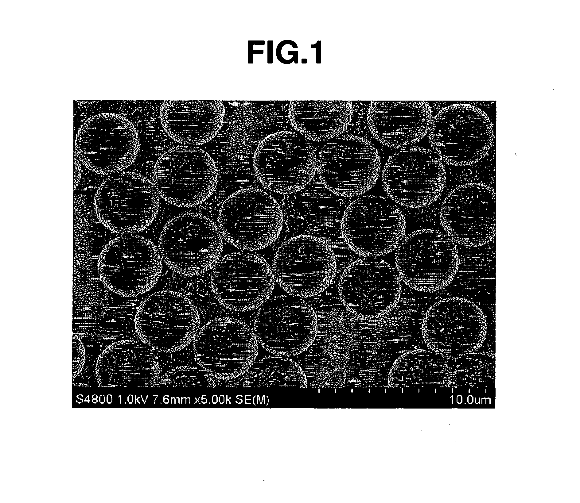
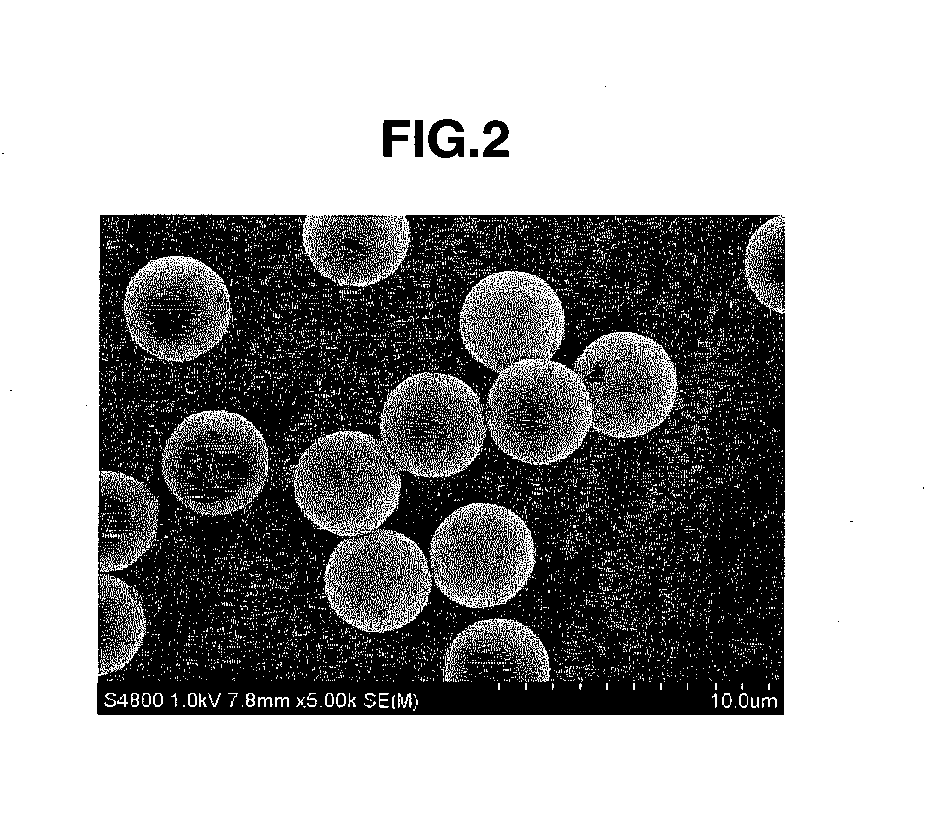
[0243] The particle-containing solution thus obtained was subjected about 3 to 5 times to washing with tetrahydrofuran (hereinafter referred to as THF) and filtration by use of a known suction filtration equipment, followed by vacuum drying, to obtain Core Particles 1. The particle diameter of the particles thus obtained was observed and measured under an SEM. The particles were spherical particles with a mean particle diameter of 3.78 μm. In addition, the Cv value was 3.7%.

[Group A1]DVB55.75g(purity 96%; DVB-960, produced by Nippon SteelChemical Co., Ltd.)[containing 3% of ethylvinylbenzene]Methacrylic acid37...

synthesis example 2

[0246] In the same manner as in Synthesis Example 1 except that the compounds set forth in the following Group A2 were used, Core Particles 2 composed of a DVB-methacrylic acid-diacrylate copolymer were obtained.

[0247] The particle diameter of the particles thus obtained was observed and measured under an SEM. The particles were spherical particles with a mean particle diameter of 5.12 μm. Besides, the Cv value was 4.0%.

[Group A2]DVB (DVB-960)61.31gMethacrylic acid40.88gNK-Ester A-DOD102.19gAcetonitrile1858.05gAIBN18.42gn-Dodecane85.51gDiethylene glycol monoethyl ether acetate92.9gDMF31.59g

[0248] Next, in the same manner as in Synthesis Example 1 except that the compounds set forth in the following Group B2 were used, a coat layer (polymer coat layer) of a styrene-methyl methacrylate copolymer was formed on the surface of each of Core Particles 2, to obtain Polymer Base Particles 2.

[0249] The particle diameter of the particles thus obtained was observed and measured under an SEM...

synthesis example 3

[0250] In the same manner as in Synthesis Example 1 except that the compounds set forth in the following Group A3 were used, Core Particles 3 composed of a DVB-methacrylic acid-dimethacrylate copolymer were obtained.

[0251] The particle diameter of the particles thus obtained was observed and measured under an SEM. The particles were spherical particles with a mean particle diameter of 4.20 μm. Besides, the Cv value was 3.8%.

[Group A3]DVB (DVB-960)51.45gMethacrylic acid51.45gNK-Ester DOD-N68.6g(produced by Shin-Nakamura Chemical Co., Ltd.)[1,10-decanediol dimethacrylate]Acetonitrile1715gAIBN14.7gn-Dodecane78.4gDiethylene glycol monoethyl ether acetate85.75g

[0252] Next, in the same manner as in Synthesis Example 1 except that the compounds set forth in the following Group B3 were used, a polystyrene coat layer (polymer coat layer) was formed on the surface of each of Core Particles 3, to obtain Polymer Base Particles 3.

[0253] The particle diameter of the particles thus obtained wa...


PUM

PropertyMeasurementUnit
Temperatureaaaaaaaaaa
Fractionaaaaaaaaaa
Fractionaaaaaaaaaa

Abstract

Conductive particles each includes a polymer base particle and a conductive layer coating the polymer base particle. Let the compressive elastic deformation characteristic KX of one conductive particle when the displacement of particle diameter of the conductive particles is X % be defined by the following formula: KX=(3 / √2)·(SX−3 / 2)·(R−1 / 2)·FX. FX is the load (N) necessary for X % displacement of the conductive particles. SX is the compressive deformation amount (mm) upon X % displacement of the conductive particles. R is the particle radius (mm) of the conductive particles. The compressive elastic deformation characteristic K50 when the displacement of particle diameter of the conductive particles is 50% is 100 to 50000 N / mm2 at 20° C., and the recovery factor of particle diameter of the conductive particles when the displacement of particle diameter of the conductive particles is 50% is not less than 30% at 20° C.

Description

CROSS-REFERENCE TO RELATED APPLICATION [0001] This non-provisional application claims priority under 35 U.S.C. §119(a) on Patent Application No. 2006-269028 filed in Japan on Sep. 29, 2006, the entire contents of which are hereby incorporated by reference. BACKGROUND OF THE INVENTION [0002] 1. Field of the Invention [0003] The present invention relates to conductive particles and a method of preparing the same. [0004] 2. Description of the Related Art [0005] In recent years, in the fields of electric and electronics materials, conductive particles have been applied to conductive materials such as liquid-crystal spacers, micro-device mounting conductive adhesives, anisotropic conductive adhesives, conductive connecting structures, etc. and put to practical use. [0006] The conductive particles for use in such conductive materials are required to show excellent properties with regard to connection resistance and connection reliability. In the conductive particles, therefore, not only t...

Claims


Application Information

Patent Timeline
IPC IPC(8): H01B1/00B05D5/12B32B5/16
CPCC08J3/12H01B1/128H01B1/20H05K3/321Y10T428/2998H05K2201/0221H05K2201/0233C08J3/126C08J2333/20H05K3/323H01B1/16H01B1/22H01B5/14
Inventor HASHIBA, TOSHIFUMIHAYAKAWA, KAZUTOSHIKUDO, SATOMIMORIYAMA, KOHEIFUJII, TSUYOSHI
Owner NIPPON CHECMICAL IND CO LTD
Learn More