Phosphor, its Production Method, and Light Emitting Apparatus

a technology of phosphor and light-emitting apparatus, which is applied in the field of phosphor, can solve the problems of insufficient red color emission luminance, decrease of luminance, and decrease of luminance of phosphor, and achieve excellent productivity, reduce luminance, and high luminance phosphor

Active Publication Date: 2008-08-21
NAT INST FOR MATERIALS SCI
View PDF7 Cites 28 Cited by
  • Summary
  • Abstract
  • Description
  • Claims
  • Application Information

AI Technical Summary

Benefits of technology

[0086]The phosphor of the present invention contains as a main component an inorganic compound containing divalent alkaline-earth element A, Si, nitrogen, and oxygen and containing as a host crystal a crystal composed of two or more phases of an inorganic crystal having the same crystal stricture as that of A2Si5N8 and A element-containing crystal (esp. A2SiO4), in which M-element is dissolved, thereby exhibits light emission at a longer wavelength than that in the cases of conventional sialon and oxynitride phosphors, so that the phosphor of the invention is regarded as high luminance phosphor. The above composition can be synthesized using Si3N4, MO (oxide of M), AO (oxide of A), or ACO3 (carbonate of A) which is stable in the air as a starting material and therefore excellent in productivity. Further, the phosphor of the present invention is chemically stable. Thus, even when exposed to an excitation source, the phosphor does not exhibit decrease of luminance and thus provides a useful phosphor which is suitably employed in VFD, FED, PDP, CRT, white LED, and the like.

Problems solved by technology

However, as a result of exposure of the phosphors to the above excitation source, there arises a problem of decrease of luminance of the phosphors due to a long term use and hence a phosphor exhibiting no decrease of luminance has been desired.
The phosphors emitting a light of red color are also known but emitting luminance of red color is not sufficient by excitation with a blue visible light.
Moreover, they are chemically unstable in some composition and thus their durability is problematic.
Further, metal or nitride such as Ca or Sr is used as a starting material, so that it is necessary to mix powders in an outside air cutoff state, thus posing a problem in terms of productivity.
However, there is a problem that the white light-emitting diode comprising a blue light-emitting diode element and the yttrium aluminum garnet-based phosphor has a characteristic of emitting a bluish-white light because of an insufficient red component and hence deflection is found in color-rendering properties.
The red phosphor described in Patent Document 12 contains cadmium and thus there is a problem of environmental pollution.

Method used


Image

  • Phosphor, its Production Method, and Light Emitting Apparatus
  • Phosphor, its Production Method, and Light Emitting Apparatus
  • Phosphor, its Production Method, and Light Emitting Apparatus

Examples


example 1

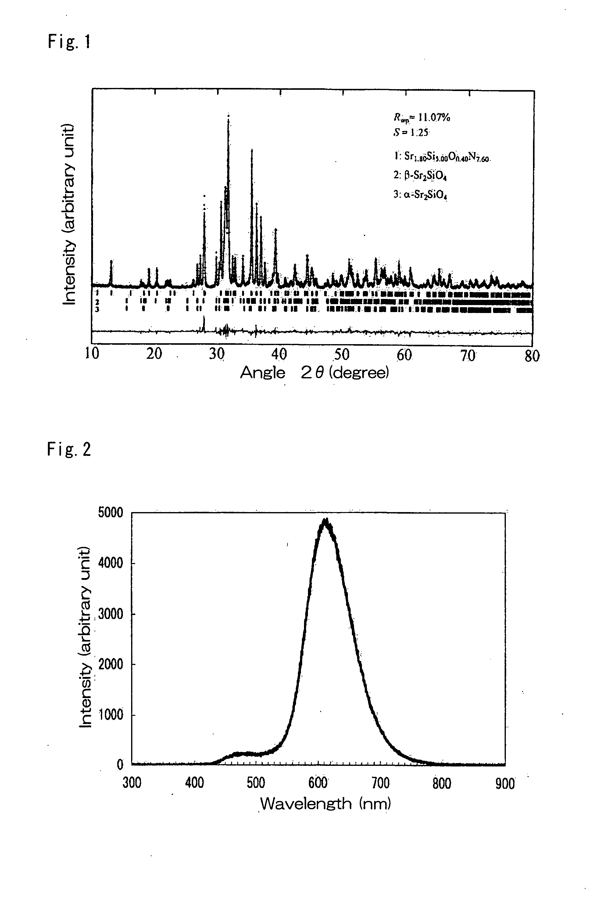
[0168]In order to synthesize a compound represented by the composition formula: Eu0.0036364Sr0.178182Si0.272727O0.181818N0.363636 (Sr2-ySi3O2N4:Euy2+, y=0.04), the silicon nitride powder having an average particle size of 0.5 μm, an oxygen content of 0.93% by weight, and an α-type content of 92%, the strontium oxide powder, and the europium oxide powder, were weighed so as to be 40.03% by weight, 57.96% by weight, and 2.01% by weight, respectively, followed by mixing with hexane added planetary ball mill using balls and pot of silicon nitride and drying with a rotary evaporator. The resultant mixture was pulverized using a pestle and mortar and mortar made of silicon nitride and allowed to fall freely into a crucible made of boron nitride having a diameter of 20 mm and a height of 20 mm through a sieve of 500 μm to fill the crucible with the powder. The filling bulk density of the powder was about 25%. The bulk density was calculated based on the weight of the placed powder aggregat...

example 2

[0176]In order to synthesize a compound represented by the composition formula: Eu0.0030769Sr0.227692Si0.230769O0.230769 N0.307692 (Sr3-ySi3O3N4:Euy2+, y=0.04), the silicon nitride powder having an average particle size of 0.5 μm, an oxygen content of 0.93% by weight, and an α-type content of 92%, the strontium oxide powder, and the europium oxide powder, were weighed so as to be 30.89% by weight, 67.56% by weight, and 1.55% by weight, respectively, followed by mixing, drying, and baking in a manner similar to the Example 1. After baking, the resulting baked product was roughly pulverized and then was pulverized by hand using a crucible and mortar made of silicon nitride sintered compact, followed by filtering through a sieve having a mesh of 30 μm. When the particle distribution was measured, the average particle size was found to be 8 μm.

[0177]Next, the synthesized compound was pulverized by means of an agate mortar and then measurement of powder X-ray diffraction was conducted us...

example 4

[0183]The silicon nitride powder, the calcium oxide powder, and the europium oxide powder, were weighed so as to be 54.53% by weight, 42.73% by weight, and 2.74% by weight, respectively, followed by mixing, drying, baking, and pulverization in a manner similar to the Example 1 to synthesize Eu0.0036364Ca0.178182Si0.272727O0.181818N0.363636 (Ca3-ySi3O3N4:Euy2+, y=0.04)


PUM

PropertyMeasurementUnit
wavelengthaaaaaaaaaa
temperatureaaaaaaaaaa
particle sizeaaaaaaaaaa

Abstract

An object of the present invention is to provide an inorganic phosphor, particularly, an oxynitride phosphor containing alkaline earths which has a higher luminance than that of conventional sialon phosphors activated with a rare earth, and is chemically stable.By baking a raw material mixture containing at least silicon nitride powder, M element containing inorganic substance, and A element containing inorganic substance at a temperature range of 1200° C. to 2200° C. in a nitrogen atmosphere, a phosphor comprising an inorganic composition containing at least M Element, A Element, silicon, oxygen, and nitrogen (wherein M Element is one or two or more elements selected from the group consisting of Mn, Ce, Pr, Nd, Sm, Eu, Tb, Dy, Ho, Er, Tm, and Yb, A Element is one or two or more elements selected from the group consisting of Mg, Ca, Sr, and Ba) and containing at least crystal having the same crystal structure as that of A2Si5N8 and A element-containing crystal is obtained.

Description

TECHNICAL FIELD[0001]The present invention relates to a phosphor mainly composed of an inorganic compound, its production method, and applications thereof. More specifically, the applications relate to a lighting apparatus and light-emitting apparatus for image display unit, which utilize a property possessed by the phosphor, i.e., a characteristic of emitting fluorescence having a long wavelength of 570 nm to 700 nm.BACKGROUND ART[0002]Phosphors are used for a vacuum fluorescent display (VFD), a field emission display (FED or SED), a plasma display panel (PDP), a cathode ray tube (CRT), a white light-emitting diode (LED), and the like. In all these applications, it is necessary to provide energy for exciting the phosphors in order to cause emission from the phosphors. The phosphors are excited by an excitation source having a high energy, such as a vacuum ultraviolet ray, an ultraviolet ray, an electron beam, or a blue light to emit a visible light.[0003]However, as a result of exp...

Claims


Application Information

Patent Timeline
Patent Type & Authority Applications(United States)
IPC IPC(8): C09K11/59C09K11/08
CPCC01B21/0821C01P2002/72H01L2224/8592C01P2002/84C01P2004/04C04B35/597C04B35/6261C04B35/6262C04B2235/3208C04B2235/3213C04B2235/3215C04B2235/3224C04B2235/3229C04B2235/3865C04B2235/3878C04B2235/3895C04B2235/5436C04B2235/5445C04B2235/766C04B2235/767C09K11/0883C09K11/7706C09K11/7721C09K11/7734C09K11/7749H01L33/502H01L2224/45144H01L2224/48091H01L2224/48247H01L2924/00014H01L24/45H01L2924/12041H01L2924/181C09K11/77347C09K11/77067C09K11/77217C09K11/77497H01L2924/00H01L2924/00012
Inventor HIROSAKI, NAOTOXIE, RONG-JUN
Owner NAT INST FOR MATERIALS SCI
Why Eureka
Try Eureka