Multiple laminar flow-based particle and cellular separation with laser steering

a laser steering and laser flow technology, applied in the direction of nuclear engineering, assay labels, sedimentation settling tanks, etc., can solve the problems of several hours, slow process, and other procedures are time-consuming, and achieve the effect of significant time savings and higher throughput for blood fractionation

Active Publication Date: 2009-02-05
ABS GLOBAL
View PDF4 Cites 83 Cited by
  • Summary
  • Abstract
  • Description
  • Claims
  • Application Information

AI Technical Summary

Benefits of technology

[0032]The exemplary embodiments of the present invention provide for separating components in a mixture, such as separating the various blood components of whole blood into corresponding fractions, such as a platelet fraction, a red blood cell fraction, a white blood cell fraction, and a plasma fraction. The various embodiments of the present invention provide separation of components on a continuous basis, such as within a continuous, closed system, without the potential damage and contamination of prior art methods, particularly for fractionation of blood components. The

Problems solved by technology

Nevertheless, the process is slow relative to the patience of donors and is capable of improvement for the purity of the separated platelet fraction.
Other procedures are also time consuming, often taking several hours, particularly when unused blood fractions are to be returned to the donor.
This centrifugation process is also comparatively harsh, also can result in damage to a proportion of the harvested cells, effectively reducing the usable yield of the blood fractions.
Other types of separations are also either time consuming or cannot process large-volumes of material in a timely fashion.
For example, sperm sorting, in which viable and motile sperm are isolated from non-viable or non-motile sperm, is often a time-consuming task, with severe volume restrictions.
Amplitude

Method used


Image

  • Multiple laminar flow-based particle and cellular separation with laser steering
  • Multiple laminar flow-based particle and cellular separation with laser steering
  • Multiple laminar flow-based particle and cellular separation with laser steering

Examples


Embodiment Construction

[0091]While the present invention is susceptible of embodiment in many different forms, there are shown in the drawings and will be described herein in detail specific embodiments thereof, with the understanding that the present disclosure is to be considered as an exemplification of the principles of the invention and is not intended to limit the invention to the specific embodiments illustrated.

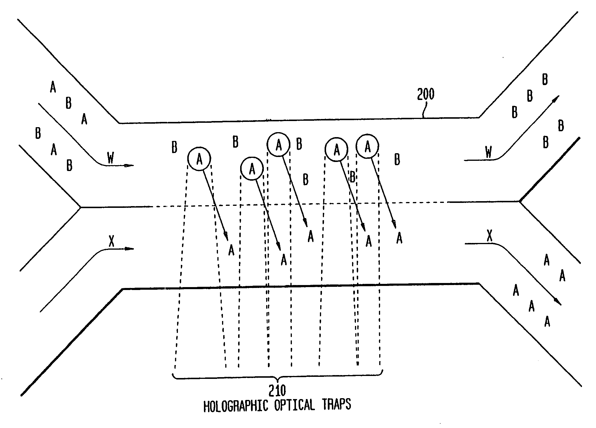
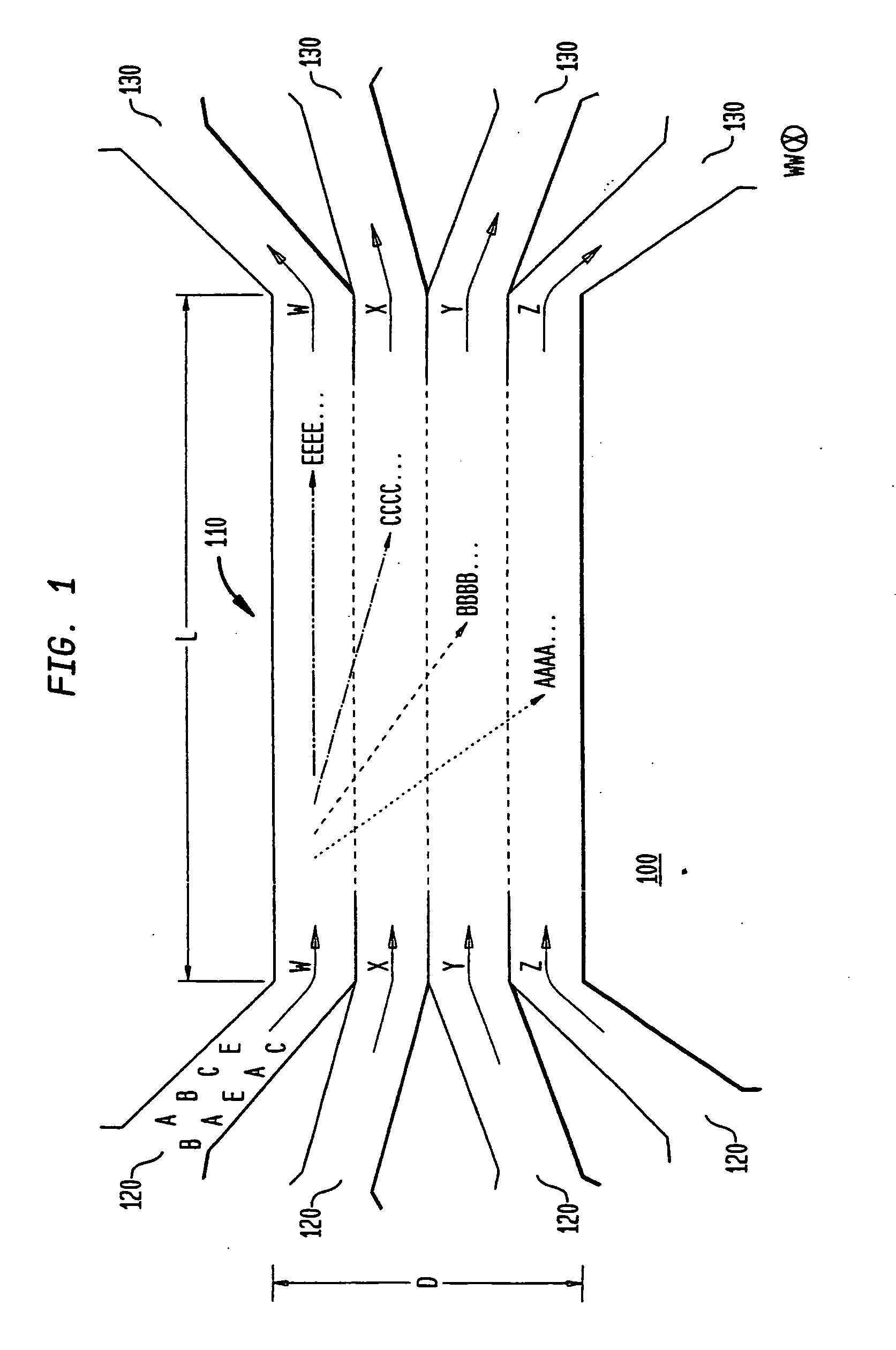
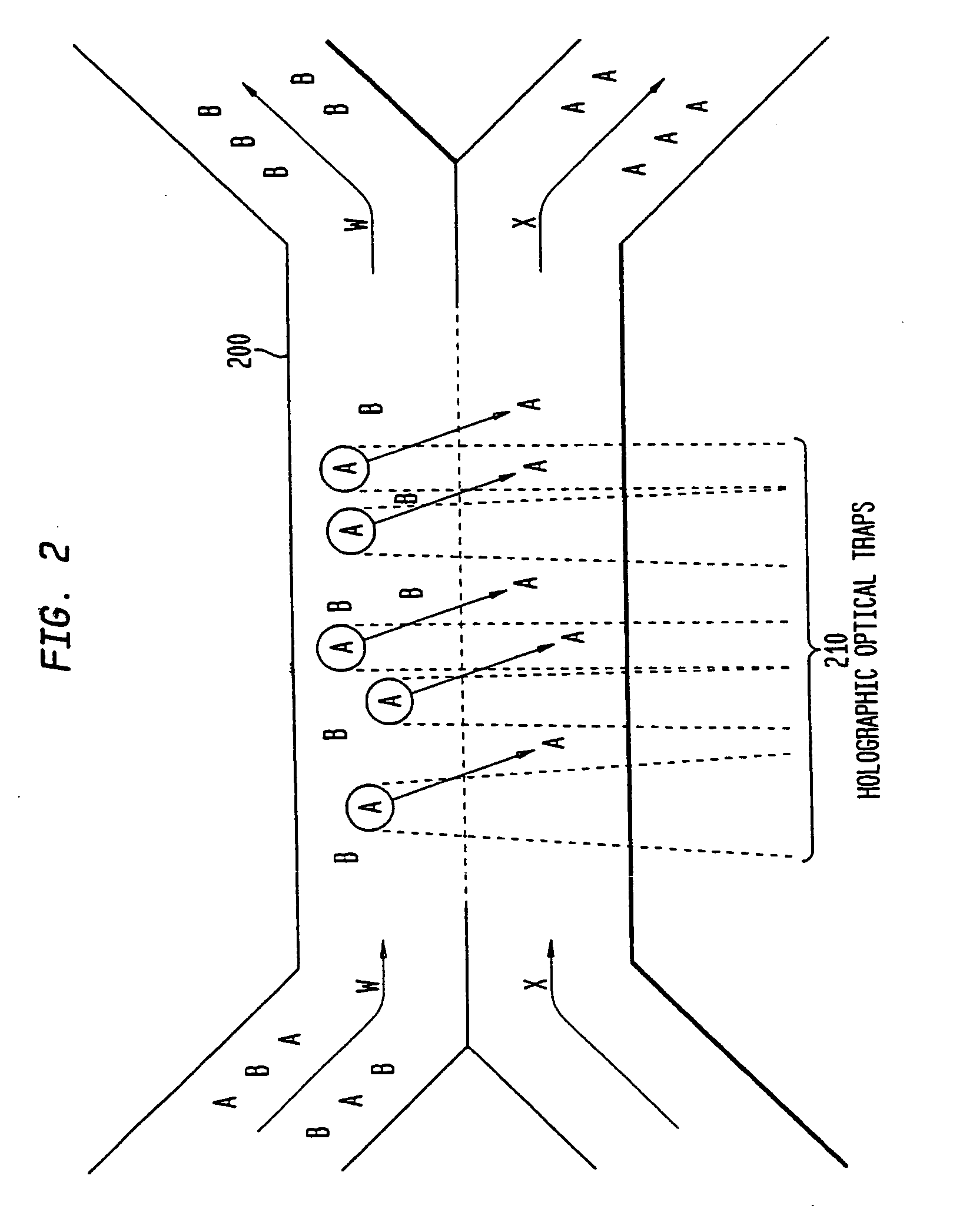
[0092]As indicated above, the various embodiments of the present invention provide for separating components in a mixture, such as separating the various blood components of whole blood into corresponding fractions, such as a platelet fraction, a red blood cell fraction, a white blood cell fraction, and a plasma fraction. The various embodiments, as described below, utilize one or more sorting channels, having a plurality of substantially laminar flows, allowing one or more components to differentially sediment from one flow into another, thereby separating the components into corresponding...


PUM


Abstract

The invention provides a method, apparatus and system for separating blood and other types of cellular components, and can be combined with holographic optical trapping manipulation or other forms of optical tweezing. One of the exemplary methods includes providing a first flow having a plurality of blood components; providing a second flow; contacting the first flow with the second flow to provide a first separation region; and differentially sedimenting a first blood cellular component of the plurality of blood components into the second flow while concurrently maintaining a second blood cellular component of the plurality of blood components in the first flow. The second flow having the first blood cellular component is then differentially removed from the first flow having the second blood cellular component. Holographic optical traps may also be utilized in conjunction with the various flows to move selected components from one flow to another, as part of or in addition to a separation stage.

Description

CROSS-REFERENCE TO RELATED APPLICATIONS AND PRIORITY CLAIMS[0001]The present invention is a continuation-in-part of Daniel M. Mueth et al., U.S. patent application Ser. No. 10 / 867,328, filed Jun. 13, 2004, entitled “Multiple Laminar Flow-Based Rate Zonal Or Isopycnic Separation With Holographic Optical Trapping Of Blood Cells And Other Static Components”, commonly assigned herewith, the contents of which are incorporated by reference herein, with priority claimed for all commonly disclosed subject matter (the “first related application”).[0002]The present invention is related to Jessica Shireman et al., U.S. Provisional Patent Application Ser. No. 60 / 571,141, filed May 14, 2004, entitled “System and Method of Sorting Blood Cells Using Holographic Laser Steering”, commonly assigned herewith, the contents of which are incorporated by reference herein, with priority claimed for all commonly disclosed subject matter (the “second related application”).[0003]The present invention is relat...

Claims


Application Information

Patent Timeline
IPC IPC(8): B01D35/30G21K1/00
CPCG02B21/32G03H1/08G03H1/2294G03H2001/0077G01N33/487G03H2225/32H05H3/04B01D21/01G03H2001/085B03C1/002B03C1/288B03C5/005G01N2015/0053G01N15/0205B01D21/0009B01L3/502761B01L2200/0652B01L2200/0668B01L2300/0864B01L2400/0454B03C2201/26G01N15/0227G01N33/491G01N33/4915G01N15/14G01N15/042G01N15/05G01N15/0631G01N15/0656G01N2015/035G01N2015/1081G01N2015/1025G01N2015/0233G01N2015/0288G01N2015/149G01N2015/045G01N15/04G01N21/6486G01N33/5091G01N2201/061G01N2458/00A61L2/08B01D21/262B03C1/00B04B13/00G01N27/447G01N27/44756G03H1/0005G21K5/08
Inventor MUETH, DANIELPLEWA, JOSEPHSHIREMAN, JESSICAANDERSON, AMYGRUBER, LEWISROSENBAUM, NEIL HARRIS
Owner ABS GLOBAL
Why Eureka
Try Eureka