
Electromagnetic wave absorber

a technology of electromagnetic radiation and absorber, which is applied in the field of electromagnetic radiation absorber, can solve the problems of increasing the tendency to emit unnecessary noise, deterioration of the environment, and misoperation of electronic devices due to emi (electro-magnetic interference), and achieves strong electromagnetic radiation absorption and high loss characteristi

Inactive Publication Date: 2009-05-28
MITSUI & CO LTD
View PDF10 Cites 64 Cited by
  • Summary
  • Abstract
  • Description
  • Claims
  • Application Information

AI Technical Summary

Benefits of technology

"The invention relates to an electromagnetic wave absorber for the GHz band, which is commonly used in electronic devices and can be affected by EMI. The technical problem addressed is the development of an effective electromagnetic wave absorber that is lightweight and can be used for both millimeter wave and GHz band applications. The existing electromagnetic wave absorbers made of soft magnetic metallic materials have limitations in their frequency range and heavy weight. Carbon-based materials have been explored as a potential solution, but their electromagnetic wave absorption capability needs further improvement. The invention proposes a new electromagnetic wave absorber that overcomes these limitations and provides better electromagnetic wave absorption capability."

Problems solved by technology

Thus, there are increasing tendencies to emit unnecessary noises.
By the way, when the frequency of the electromagnetic waves rise, the misoperations of electronic devices due to EMI (Electro-Magnetic Interference) will arise because of the degression in the noise margin due to the energy-saving of the recent electronic devices, and the deterioration of the environment of the noise in the electronic devices due to the tendency of miniaturizing and densification of electronic devices, while the electromagnetic waves becomes easy to be radiated as noise.
With respect to the soft magnetic metallic material, although it is possible to extend the threshold frequency of the material as the electromagnetic wave absorber up to about 10 GHz owing to the repression effect against the eddy currents and the effect of magnetic shape anisotropy which are obtained by forming particles into flatten shapes of not more than the skin depth, however, such a magnetic material has a heavy weight, and thus, it is impossible to achieve a light weight electromagnetic wave absorber.
However, its electromagnetic wave absorption capability does not reach a sufficient level, and thus, the development of an electromagnetic wave absorber excellent in the electromagnetic wave absorption capability which can be used even for the millimeter wave range has been sought.
Since the electromagnetic wave absorber described in the patent literature 1 is prepared by admixing graphite and resin in nearly equal proportions, it can hardly sustain the mechanical characteristics, such as toughness, of the resin.
Further, the graphite makes the surface roughness rough, and this fact will cause an increase in the exfoliation of surface layer and a decrease in surface conductivity.
The supporting technology disclosed in the patent literature 2 is extremely difficult, and the leaved material to be supported and the leaved carbon nanotubes mutually independently agglomerate, and which is followed by the deterioration of the electromagnetic wave absorption capability.
Although such dropping off and oxidation can be solved by involving the material to be supported into the carbon nanotubes, the yield of such involved form is extremely low.
The electromagnetic wave absorber described in the patent literature 4 requires a metallic thin film, such as Ag, Cu, Au or Pt, of about 10 nm in thickness between two layers of carbon nanotube containing layers, and thus the manufacturing process becomes complicated one and costly.
Therefore, the formability of the electromagnetic wave absorber is not good, and the usage thereof will be restricted

Method used


Image

  • Electromagnetic wave absorber
  • Electromagnetic wave absorber
  • Electromagnetic wave absorber

Examples


synthetic example 1

[0128]By the CVD process, carbon fibrous structures were synthesized from toluene as the raw material.

[0129]The synthesis was carried out in the presence of a mixture of ferrocene and thiophene as the catalyst, and under the reducing atmosphere of hydrogen gas. Toluene and the catalyst were heated to 380° C. along with the hydrogen gas, and then they were supplied to the generation furnace, and underwent thermal decomposition at 1250° C. in order to obtain the carbon fibrous structures (first intermediate).

[0130]The generation furnace used for the carbon fibrous structures (first intermediate) is illustrated schematically in FIG. 8. As shown in FIG. 8, the generation furnace 1 was equipped at the upper part thereof with a inlet nozzle 2 for introducing the raw material mixture gas comprising toluene, catalyst and hydrogen gas as aforementioned into the generation furnace 1. Further, at the outside of the inlet nozzle 2, a cylindrical-shaped collision member 3 was provided. The colli...

synthetic example 2

[0140]By the CVD process, carbon fibrous structures were synthesized using a part of the exhaust gas from the generation furnace as a recycling gas in order to use as the carbon source the carbon compounds such as methane, etc., included in the recycling gas, as well as a fresh toluene.

[0141]The synthesis was carried out in the presence of a mixture of ferrocene and thiophene as the catalyst, and under the reducing atmosphere of hydrogen gas. Toluene and the catalyst as a fresh raw material were heated to 380° C. along with the hydrogen gas in a preheat furnace, while a part of the exhaust gas taken out from the lower end of the generation furnace was used as a recycling gas. After it was adjusted to 380° C., it was mixed with the fresh raw material gas on the way of the supplying line for the fresh raw material to the generation furnace. The mixed gas was then supplied to the generation furnace.

[0142]The composition ratio in the recycling gas used were found to be CH4 7.5%, C6H6 0....

examples 1-4

[0155]2, 5, 10, or 25% by weight of the carbon fibrous structures obtained by Referential Example 1 were added to polycarbonate resin (Panlite® L-1225LL, manufactured by TEIJIN Chemicals Ltd.). The obtained composite was then subjected to injection press molding using an injection press machine (MDIP-1400, manufactured by MEIKI Co. Ltd.) in order to obtain a molded plate of 4.8 mm in thickness Sample plate was prepared by cutting a piece of 460 mm×460 mm in size from the molded plate.

[0156]The electromagnetic wave absorbing properties of the obtained samples were examined in accordance with the previously described method. As the results, with respect to all the samples in which the addition amount of the carbon fibrous structures were 2, 5, 10, and 25-% by weight, respectively, high electromagnetic wave absorbing property was demonstrated to the whole range of the examined frequencies of 1-20 GHz, particularly, to the frequencies of not less than 10 GHz, as shown in Table 5.

TABLE 5...


PUM

PropertyMeasurementUnit
diameteraaaaaaaaaa
frequencyaaaaaaaaaa
frequencyaaaaaaaaaa

Abstract

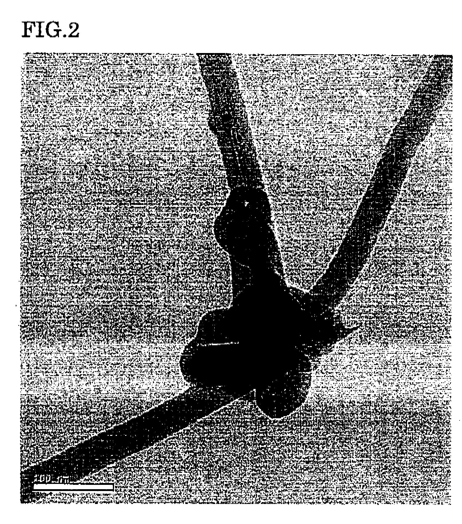
By using a high electromagnetic wave absorbing loss material and adding it in a small amount to a matrix, an electromagnetic wave absorber useful for GHz band, which can demonstrate the electromagnetic wave absorption capability without ruining characteristics of the matrix, and can enjoy a good formability and a low manufacturing cost, is provided.The disclosed is an electromagnetic wave absorber which is characterized in that carbon fibrous structures are contained in the matrix, at a rate of 0.01-25% by weight based on the total weight, wherein the carbon fibrous structure comprises a three dimensional network of carbon fibers each having an outside diameter of 15-100 nm, wherein the carbon fibrous structure further comprises a granular part with which the carbon fibers are tied together in the state that the concerned carbon fibers are externally elongated therefrom, and wherein the granular part is produced in a growth process of the carbon fibers.

Description

TECHNICAL FIELD[0001]This invention relates to an electromagnetic wave absorber, especially, to an electromagnetic wave absorber for gigahertz (GHz) band.BACKGROUND ART[0002]Recently, high-speed processing of electronic devices has been accelerated, and the operating frequencies for ICs such as LSIs or microprocessors have been ascended rapidly. Thus, there are increasing tendencies to emit unnecessary noises. In addition, in the field of communications, 2 GHz has been utilized for the next generation multimedia mobile communication, 2-30 GHz for wireless LAN, and high-speed communication network using optical fibers, as well as 5.8 Hz for ETS (Electronic Toll Collection System) and 76 GHz for AHS (advanced cruise-assist highway system) in the field of ITS (Intelligent Transport System), etc. Further, the range of using the high frequency such as 0 Hz band is expected to be going to expand rapidly in the future.[0003]By the way, when the frequency of the electromagnetic waves rise, ...

Claims


Application Information

Patent Timeline
Patent Type & Authority Applications(United States)
IPC IPC(8): H01Q17/00
CPCB82Y30/00C01B31/02D01F9/127H05K9/009H01Q17/005H05K9/0083H01Q17/002C01B32/05
Inventor UMISHITA, KAZUNORIOKUBO, TSUYOSHI
Owner MITSUI & CO LTD
Learn More