Device For Reducing Dibenzodioxin Emissions, Dibenzofuran Emissions And Particle Emissions

a dibenzofuran and dibenzodioxin technology, applied in combination devices, exhaust treatment, using liquid separation agents, etc., can solve the problems of increasing the counterpressure of exhaust gas, difficult to apportion the reducing agent, and difficult to reduce nitric oxide using the scr method in internal combustion engines operating in vehicles. achieve the effect of reducing pcdd emissions and pcdf emissions

Active Publication Date: 2009-08-13
MAN NUTZFAHRZEUGE AG
View PDF14 Cites 25 Cited by
  • Summary
  • Abstract
  • Description
  • Claims
  • Application Information

AI Technical Summary

Benefits of technology

[0028]It is an object of the invention to reduce PCDD emissions and PCDF emissions as well as the emi...

Problems solved by technology

Nitric oxide reduction using the SCR method in internal combustion engines operating in vehicles is difficult because of the changing operating conditions, which makes it difficult to apportion the reducing agent.
Due to this difference, particle filters are subject to blockage, which increases the exhaust gas counterpressure and lowers engine performance.
As a result, the achievable NO2 proportions are limited at high temperatures due to this thermodynamic limitation.
The disadvantage of this method is that the NO2 formed at the particle filter can only be used for oxidation of particles which have been separated out downstream of the catalytically active layer for NO oxidation, that is, inside the filter medium.
However, if a layer of separated particles, or a filter cake as it is called, should form on the filter surface and, therefore, on the catalytically active layer, the NO oxidation catalyzer lies downstream of the filter cake so that the soot particles separated out at that location cannot be oxidized by means of NO2 from the NO oxidation catalyzer arranged on the particle filter.
Another problem arising from the coating of the particle filter is that the geometric surfaces of the filter are appreciably smaller than those of the catalyzer substrates that are normally used.
This leads to a relatively lar...

Method used


Image

  • Device For Reducing Dibenzodioxin Emissions, Dibenzofuran Emissions And Particle Emissions
  • Device For Reducing Dibenzodioxin Emissions, Dibenzofuran Emissions And Particle Emissions
  • Device For Reducing Dibenzodioxin Emissions, Dibenzofuran Emissions And Particle Emissions

Examples


Embodiment Construction

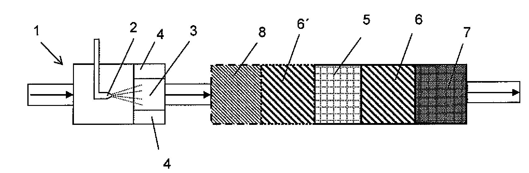
[0066]An exhaust gas after-treatment system for selective catalytic reduction and for the reduction of solids particles in the exhaust gas of an internal combustion engine is shown schematically in FIG. 1. The exhaust gases, symbolized by the arrows in FIG. 1, which are generated by the combustion processes in an internal combustion engine (not shown) initially enter an exhaust gas processing system 1 in which a reducing agent is added to the hot exhaust gas as close to the engine as possible. As is common practice in motor vehicles with SCR catalyzers, the reducing agent is an aqueous urea solution but, of course, it is also possible to add urea in solid form as has already been extensively described in the pertinent technical literature. Further, it is possible to add ammonia as a reducing agent which is obtained at another place, e.g., under more favorable thermal conditions, from a material which splits off ammonia. Depending on the operating parameters of the internal combustio...


PUM

PropertyMeasurementUnit
Thicknessaaaaaaaaaa
Thicknessaaaaaaaaaa
Pore sizeaaaaaaaaaa

Abstract

A transition metal-containing catalyzer is arranged on a particle filter installed in the exhaust gas line of an internal combustion engine and cannot be separated therefrom without being destroyed. To reduce emissions, at least one molecular sieve which retains polychlorinated dibenzodioxins and polychlorinated dibenzofurans is arranged between the transition metal-containing catalyzer and the exhaust gas outlet. Further, the input side of the molecular sieve and/or the output side of the catalyzer has an oxidation activity for hydrocarbons, polychlorinated dibenzodioxins and polychlorinated dibenzofurans upstream of the molecular sieve.

Description

BACKGROUND OF THE INVENTION[0001]1. Field of the Invention[0002]The subject matter of the invention is a device for reducing dibenzodioxin emissions, dibenzofuran emissions and particle emissions in lean-burn internal combustion engines such as diesel engines and gasoline engines with direct injection.[0003]2. Description of the Related Art[0004]Along with solids particles, nitric oxides are some of the limited components of exhaust gas which are formed during combustion processes. Permissible emissions of these components continue to be lowered. At present, various methods are employed to minimize these exhaust gas components in internal combustion engines for motor vehicles. Reduction of nitric oxides is usually accomplished by means of catalyzers; reducing agents are additionally required in oxygen-rich exhaust to increase selectivity and NOX conversion. These methods have come to be known under the umbrella term of SCR (Selective Catalytic Reduction) methods. They have been used...

Claims


Application Information

Patent Timeline
IPC IPC(8): F01N3/035
CPCB01D53/9431F01N13/0097B01D53/9472B01D2251/2062B01D2253/108B01D2253/304B01D2253/308B01D2255/102B01D2255/1021B01D2255/206B01D2255/20707B01D2255/20723B01D2255/2073B01D2255/20738B01D2255/20761B01D2255/20769B01D2255/20776B01D2255/502B01D2255/504B01D2255/9022B01D2255/915B01D2257/404B01D2257/7022B01D2257/7027B01D2258/012B01D2258/014B01D2259/4566B01J37/0244B01J37/0246F01N3/035F01N3/0821F01N3/106F01N3/2073F01N2240/40F01N2330/14F01N2330/22F01N2510/063F01N2570/00F01N2610/02Y02T10/22B01D53/9445Y02T10/12
Inventor DORING, ANDREAS
Owner MAN NUTZFAHRZEUGE AG
Why Eureka
Try Eureka