
Positive resist composition and method of forming resist pattern

a composition and resist technology, applied in the field of positive resist composition and a method of forming a resist pattern, can solve the problems of low resolution of chemically amplified resist using phs resin as the base resin component, short wavelength of light less than 248 nm, and insufficient 193 nm, etc., to achieve excellent lithographic properties and less defects

Active Publication Date: 2009-09-17
TOKYO OHKA KOGYO CO LTD
View PDF11 Cites 6 Cited by
  • Summary
  • Abstract
  • Description
  • Claims
  • Application Information

AI Technical Summary

Benefits of technology

[0024]According to the invention, a positive resist composition and a resist pattern forming method having less defects and exhibiting excellent lithographic properties can be provided.BEST MODES FOR CARRYING OUT THE INVENTIONPositive Resist Composition

Problems solved by technology

However, since the PHS resins include an aromatic ring such as a benzene ring, transparency to light having a short wavelength of shorter than 248 nm, that is, 193 nm is not sufficient.
Hence, there is a problem in that the chemically amplified resist using PHS resins as base resin components exhibits low resolution in a process of using light of 193 nm.

Method used


Image

  • Positive resist composition and method of forming resist pattern
  • Positive resist composition and method of forming resist pattern
  • Positive resist composition and method of forming resist pattern

Examples


synthesis example 1

[0327]In a container purged with nitrogen were placed 1080 g of methyl ethyl ketone (MEK), 50 g of MEK solution dissolved with 23 mg of sulfuric acid, 352 g of a monomer Ma, 265 g of a monomer G, and 186 g of a monomer Oa. They were made into a solution to prepare a homogeneous “monomer solution”. In another container purged with nitrogen was placed 52 g of MEK and 26 g of 2,2′-azobisisobutylate dimethyl (MAIB) to prepare a homogeneous “initiator solution”. 680 g of MEK was placed in a reactor fitted with a stirrer and a cooler. The reactor inside was purged with nitrogen and heated to 79° C. The monomer solution and the initiator solution kept at room temperature (about 25° C.) were dropped into the reactor kept at 79 to 81° C., using a metering pump, at a given rate in 4 hours. After the completion of the dropping, the reactor inside was kept at 80 to 81° C. for 2 hours to conduct ageing and then cooled to room temperature, followed by taking-out of the polymerization mixture.

[032...

synthesis example 2

[0330]A copolymer (A)-2 was prepared in the same manner as in Synthesis Example 1 except that the amount of sulfuric acid used was changed to 34 mg. There are shown, in Table 1, the kind of the acid used in preparation of the copolymer, the concentration (mass ppm) of the acid in the reaction system, and the measurement results of the Mw, Mw / Mn and proportions of structural units, of the copolymer thus obtained.

synthesis example 3

[0331]A copolymer (A)-3 was prepared in the same manner as in Synthesis Example 1 except that the amount of sulfuric acid used was changed to 39 mg. There are shown, in Table 1, the kind of the acid used in preparation of the copolymer, the concentration (mass ppm) of the acid in the reaction system, and the measurement results of the Mw, Mw / Mn and proportions of structural units, of the copolymer thus obtained.


PUM

PropertyMeasurementUnit
wavelengthaaaaaaaaaa
pKaaaaaaaaaaa

Abstract

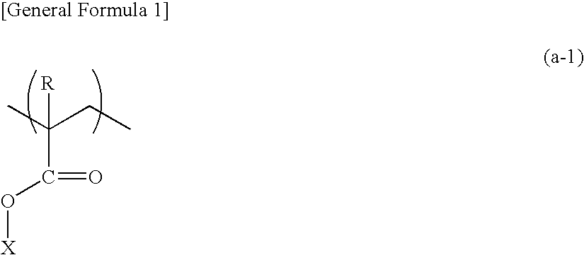
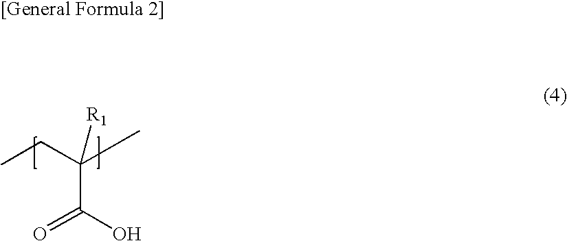
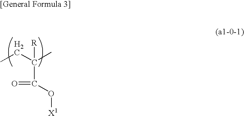
Provided are a positive resist composition and a resist pattern forming method having fewer defects and superior lithographic characteristics. The positive resist composition includes a resin component (A) which has on a main chain a structural unit derived from an (α-lower alkyl)acrylate ester and exhibits increased alkali solubility under the action of an acid, and an acid generating component (B) which generates the acid upon irradiation with radiation, in which the resin component (A) is a copolymer having at least two structural units which is obtained by incorporating an acid when polymerizing at least one monomer for the production thereof.

Description

TECHNICAL FIELD[0001]The present invention relates to a positive resist composition and a method of forming a resist pattern.[0002]Priority is claimed on Japanese Patent Application No. 2005-137777, filed May 10, 2005, the content of which is incorporated herein by reference.BACKGROUND ART[0003]In recent years, in the production of semiconductor device and liquid crystal display device, advances in lithography techniques have led to rapid progress in the miniaturization of semiconductor device and liquid crystal display device. Typically, these techniques for achieving further miniaturization involve shortening of the wavelength of the exposure light source. Until recently, ultraviolet radiation such as g-lines and i-lines have been used as the exposure light source, but recently, mass production using KrF excimer lasers (248 nm) has been employed, and even ArF excimer lasers (193 nm) are now starting to be introduced. In addition, lithography techniques using F2 excimer lasers (157...

Claims


Application Information

Patent Timeline
Patent Type & Authority Applications(United States)
IPC IPC(8): G03F7/20G03F7/004
CPCG03F7/0397C08F220/28Y10S430/111C08F220/283C08F220/38C07C2603/74C08F220/281
Inventor MUROI, MASAAKIATSUCHI, KOTANAKAMURA, TAKAHIROYAMADA, MASAKAZUSAISYO, KENSUKETAKESHITA, MASARUYAMAGISHI, TAKANORIOIKAWA, TOMO
Owner TOKYO OHKA KOGYO CO LTD
Learn More