

Resonant power factor correction converter
a power factor and converter technology, applied in the direction of electric variable regulation, process and machine control, instruments, etc., can solve the problems of transformer design difficulties, high current stress, and increase the loss of mosfet, so as to reduce the burden of low-voltage-drop semiconductor switches and high current stress
- Summary
- Abstract
- Description
- Claims
- Application Information
AI Technical Summary
Benefits of technology
Problems solved by technology
Method used
Image

Examples
first embodiment
[0045]FIG. 4 illustrates an exemplary schematic diagram of the power train components of the power converter 100 of FIG. 3. The power converter 100 shown in FIG. 4 is configured to include an LLC resonant half-bridge converter followed by buck-type converters. The power source 110 generates the input AC power supply voltage VACin. A capacitor C1, a capacitor C2, a transformer TX3, and an inductor L2 form a line filter for filtering out EMI. The inductor L2 acts as a differential mode filter to filter out the resonant-frequency current. Diodes D1, D2, D3, and D4 form a full-wave bridge rectifier configured to rectify the input line voltage. A capacitor C3, a capacitor C4, a capacitor C5, an inductor L1, a transistor Q1, a transistor Q2, and an isolation transformer TX1 form a resonant half-bridge converter. The transistors Q1 and Q2 function as switches. The capacitor C3 and the capacitor C4 form both the half-bridge center tap as well as input line filtering. In some embodiments, a ...
second embodiment
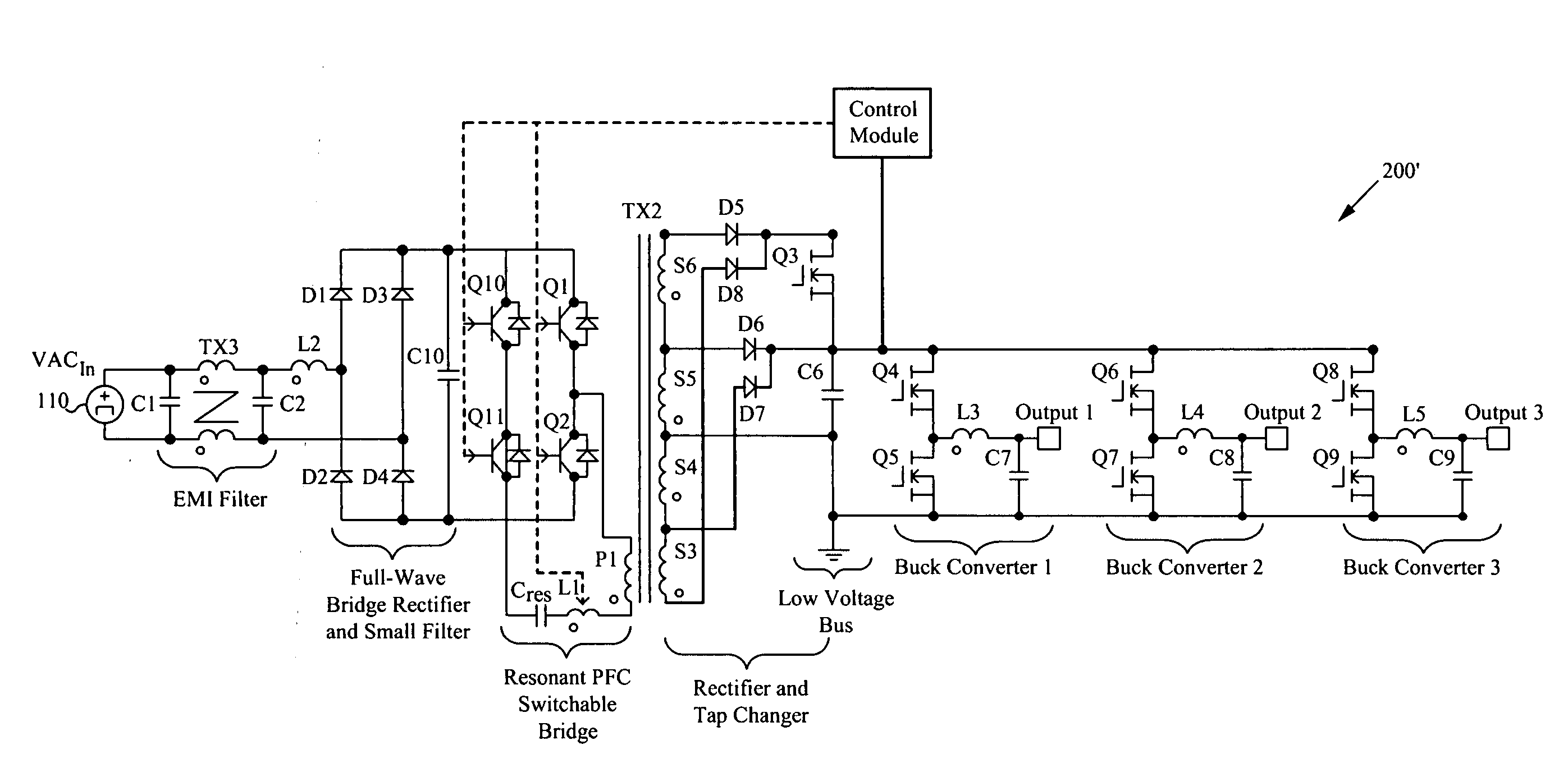
[0052]FIG. 5 illustrates an exemplary schematic diagram of the power train components of the power converter of FIG. 3. The power converter 100′ of FIG. 5 is similar to the power converter 100 shown in FIG. 4, except that the transformer TX1 is replaced by the transformer TX2. The transformer TX2 includes four transformer secondaries instead of two transformer secondaries as in the transformer TX1. Each of the four transformer secondaries of the transformer TX2 is coupled to a rectifier, specifically the diodes D5, D6, D7, D8. The diodes D5, D6, D7, D8 provide rectification of the resonant current output from the transformer TX2.
[0053]The power converter 100′ also differs from the power converter 100 in that the power converter 100′ includes a transistor Q3 coupled to each of the additional two transformer secondaries. In some embodiments, the transistor Q3 is a MOSFET. In other embodiments, the transistor Q3 can be any other type of semiconductor switching device. The transistor Q3...
third embodiment
[0056]FIG. 6 illustrates an exemplary schematic diagram of the power train components of the power converter of FIG. 3, including a switchable bridge. The power converter 200 of FIG. 6 is similar to the power converter 100′ shown in FIG. 5, except that the half-bridge converter is replaced by a switchable bridge converter. Specifically, the capacitors C3 and C4 of the power converter 100′ are replaced by transistors Q10 and Q11, respectively, in the power converter 200. The transistors Q1, Q2, Q10, Q11, the capacitor C5, the inductor L1, and the isolation transformer TX2 form a resonant PFC switchable bridge converter. The function of the two capacitors C3 and C4 (FIG. 5) is incorporated into the resonant capacitor Cres of FIG. 6. The DC bias voltage that is blocked by the capacitors C3 and C4 (FIG. 5) is added to the AC voltage across resonant capacitor Cres. Further, an additional capacitor C10 is coupled across the output of the full-wave bridge rectifier to function as a filter,...
PUM
 Abstract
Description
Claims
Application Information