Electroless plating solution, method for electroless plating using the same and method for manufacturing circuit board

Active Publication Date: 2010-01-07
C UYEMURA & CO LTD
View PDF14 Cites 10 Cited by
  • Summary
  • Abstract
  • Description
  • Claims
  • Application Information

AI Technical Summary

Benefits of technology

[0017]With the use of the electroless plating solution according to the present invention, containing a sulfur-based organic compound having a cyclic group, plating metal may be deposited in the trench or in the via without generating voids or seams. The electroless plating solution may thus be used to advantage for manufacturing a printed circuit board capable of handling high speed signals or a printed circuit board having a high interconnect density. Additionally, it may be used in stability for a prolonged time even under high alkaline conditions.
[0018]An electroless plating solution according to an embodiment of the present invention is now described in detail.
[0019]An electroless plating solution of the present embodiment contains a water-soluble metal salt such as water-soluble cupric salt or a water-soluble nickel salt as a main component. The electroless plating solution also contains at least one reducing agent such as formaldehyde, paraformaldehyde, glyoxylic acid or a salt thereof, hypophorous acid or a salt thereof, or dimethylaminoborane. The electroless plating solution further contains a chelating agent such as ethylene diamine tetraacetate tetrasodium or sodium potassium tartarate, and a leveler such as at least one sulfur-based organic compound.
[0020]The electroless plating solution of the present embodiment contains a water-soluble metal salt such as water-soluble cupric salt or a water-soluble nickel salt as a principal component. By having the water-soluble cupric salt or the wa

Problems solved by technology

However, with this semi-additive method, the following problem arises as the line width or the pattern pitch becomes finer.
That is, misregistration or development defects tend to be produced as a result of formation of the resist, thus possibly producing line breakage or circuit shorting.
However, this etching process may give breakage of useful circuit portions or circuit shorting due to insufficient etching.
However, even with this full additive method, the following problems arise with further refinement of the line width or the pattern pitch.
That is, misregistration or development defects tend to be produced as a result of formation of the resist, thus possibly producing line breakage or circuit shorting.
There are cases where the insulation performance between the circuits tends to be lowered due to the catalyst left, thus possibly

Method used


Image

  • Electroless plating solution, method for electroless plating using the same and method for manufacturing circuit board
  • Electroless plating solution, method for electroless plating using the same and method for manufacturing circuit board

Examples


example 1

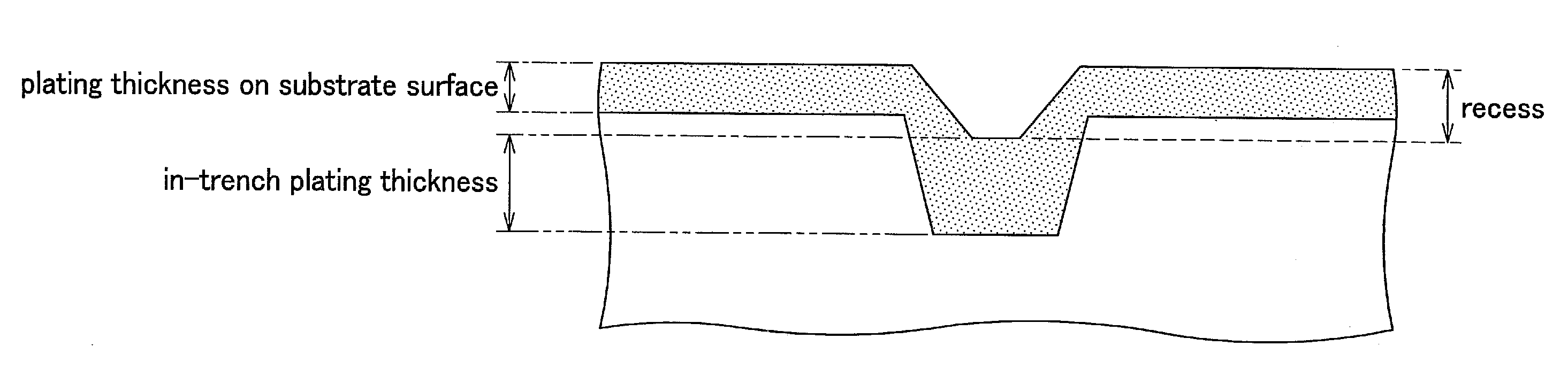
[0055]Using a laser working device, manufactured by Hitachi Via Mechanics, Ltd., usable for via opening, a trench of 20 μm in width and 13 μm in depth was formed in a board prepared by applying a general insulating resin (ABF-GX13 manufactured by Ajinomoto Fine-Techno Co., Inc.)

[0056]A catalyst affording process (Thru-Cup process of C. Uyemura & Co., Ltd.: a cleaner conditioner ACL-009, a pre-dip PED-104, catalyst AT-105 and an accelerator AL-106) was then carried out to afford a catalyst (seed layer). Using an electroless copper plating solution, electroless copper plating was carried out for two hours under a temperature condition of 70° C. to fill a trench with plating copper to form a copper plating film. After the plating operation, the filling state of the trench was measured by observing its cross section. The used electroless copper plating solution was of the following composition:

Composition of an Electroless Copper Plating Solution (Example 1)

[0057]copper sulphate: 0.04 m...

example 2

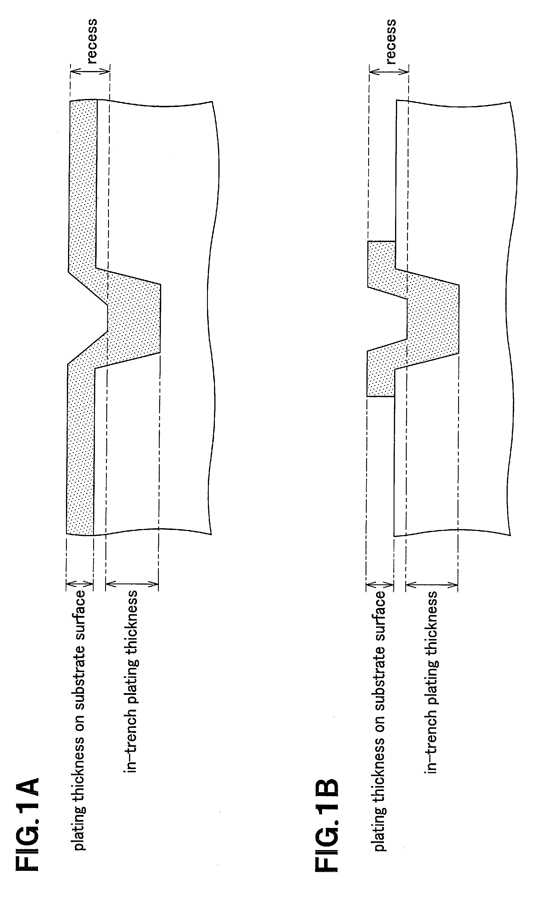
[0064]As in Example 1, a masking tape (851T manufactured by Sumitomo 3M Limited) was applied to a board on which a general insulating resin (ABF-GX13 manufactured by Ajinomoto Fine-Techno Co., Inc.) was formed. The masking tape in its entirety was processed using a laser working device used for via opening (manufactured by Hitachi Via Mechanics, Ltd.) to form a trench of 10 μm in width and 16 μm in depth in the insulating resin.

[0065]A catalyst affording process (Thru-Cup process of C. Uyemura & Co., Ltd.: a cleaner conditioner ACL-009, a pre-dip PED-104, a catalyst AT-105 and an accelerator AL-106) was then carried out to afford a catalyst (seed layer). The masking tape was then removed to afford the catalyst only into the trench.

[0066]Then, electroless copper plating was carried out for two hours under a temperature condition of 60° C. using an electroless copper plating solution, to fill the trench with plating copper to form a copper plating film. After the plating, the filling ...


PUM

PropertyMeasurementUnit
Massaaaaaaaaaa
Massaaaaaaaaaa
Concentrationaaaaaaaaaa

Abstract

Disclosed is an electroless plating solution exhibiting a good plating metal filling performance even for larger trenches or vias of several to one hundred and tens of μm, in a manner free from voids or seams, and allowing maintenance of stabilized performance for prolonged time.
The electroless plating solution contains at least a water-soluble metal salt, a reducing agent for reducing metal ions derived from the water-soluble metal salt, and a chelating agent. In addition, the electroless plating solution contains a sulfur-based organic compound as a leveler having at least one aliphatic cyclic group or aromatic cyclic group to which may be linked at least one optional substituent. The aliphatic cyclic group or the aromatic cyclic group contains optional numbers of carbon atoms, oxygen atoms, phosphorus atoms, sulfur atoms and nitrogen atoms.

Description

TECHNICAL FIELD OF THE INVENTION[0001]This invention relates to an electroless plating solution that is able to fill a trench or a via formed in, for example, a printed circuit board in a manner free from electroless plating solution, and to a method for manufacturing a circuit board using the solution.BACKGROUND OF THE INVENTION[0002]For manufacturing a multilevel circuit board having fine interconnects with a line width of 20 μm and a pattern pitch of 20 μm, a wide variety of plating methods have so far been proposed. A semi-additive method, as typical of these methods, is such a method in which a circuit board is subjected to electroless copper plating as a substrate for electrical copper plating in forming a copper circuit. A circuit pattern is then formed by a resist and the copper circuit is formed by electrical copper plating.[0003]However, with this semi-additive method, the following problem arises as the line width or the pattern pitch becomes finer. That is, misregistrati...

Claims


Application Information

Patent Timeline
IPC IPC(8): B05D1/18
CPCC23C18/1607C23C18/30C23C18/31H05K3/422C23C18/40C23C18/405C23C18/34
Inventor HOTTA, TERUYUKIISHIZAKI, TAKAHIROKAWASE, TOMOHIROTAKEUCHI, MASAHARU
Owner C UYEMURA & CO LTD
Why Eureka
Try Eureka