

Process for forming catalyst layer, and process for producing membrane/electrode assembly for polymer electrolyte fuel cell
- Summary
- Abstract
- Description
- Claims
- Application Information
AI Technical Summary
Benefits of technology
Problems solved by technology
Method used
Image

Examples
examples
[0368]Now, the present invention will be described in further detail with reference to Examples. However, it should be understood that the present invention is by no means restricted by such Examples.
[0369]Examples 1, 2 and 3 are Working Examples of the present invention, and Examples 4 and 5 are Comparative Examples.
EW
[0370]EW of polymer (P) was obtained by the following method.
[0371]Two types of polymers, of which EW is preliminarily known by titration (one having EW of 1,000 g / equivalent and one having EW of 909 g / equivalent), are prepared, and with respect to two types of membranes (thickness: 200 μm) made of the respective polymers, the peak intensity based on a sulfur atom is measured by means of a fluorescent X-ray (RIX3000, manufactured by Rigaku Corporation), whereupon a calibration curve showing the relation between the peak intensity and EW, is prepared. The polymer (P) is pressed at the after-mentioned TQ value temperature to prepare a membrane having a thickness of 200 ...
preparation examples
[0401]The compound (m12) was prepared by the following preparation route.
Preparation of Compound (a2)
[0402]Compound (a2) was prepared in the same manner as the method disclosed in Example 2 in JP-A-57-176973.
Preparation of Compound (c2)
[0403]Into a 300 cm3 four-necked round-bottomed flask equipped with a Dimroth condenser, a thermometer, a dropping funnel and a glass rod provided with stirring vanes, 1.6 g of potassium fluoride (CHLOROCATCH F, manufactured by Morita Chemical Industries Co., Ltd.) and 15.9 g of dimethoxyethane were put in a nitrogen atmosphere. Then, the round-bottomed flask was cooled in an ice bath, and 49.1 g of compound (b11) was dropwise added from the dropping funnel over a period of 32 minutes at an internal temperature of at most 10° C. After completion of the dropwise addition, 82.0 g of compound (a2) was dropwise added from the dropping funnel over a period of 15 minutes. No substantial increase of the internal temperature was observed. After completion of ...
production example 1
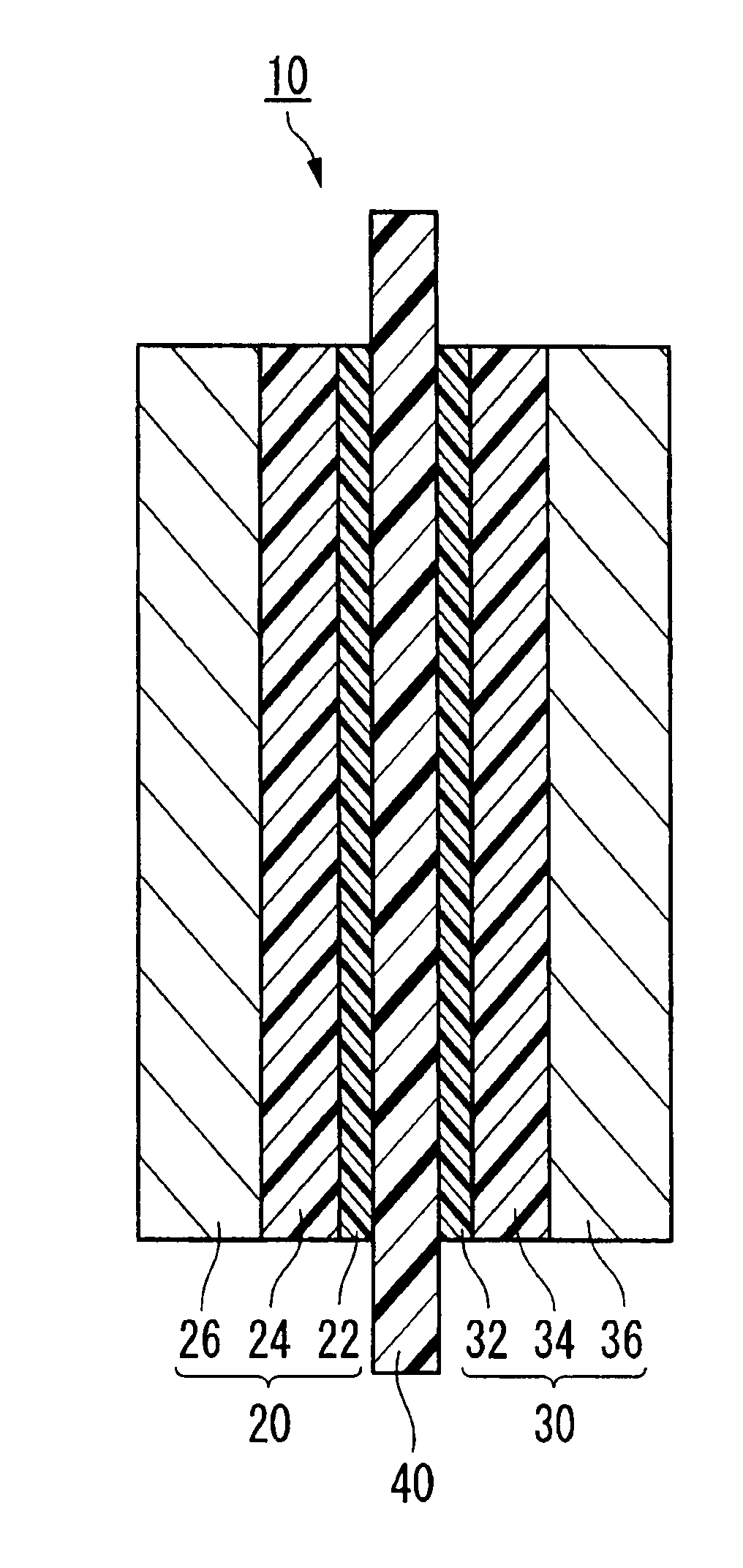
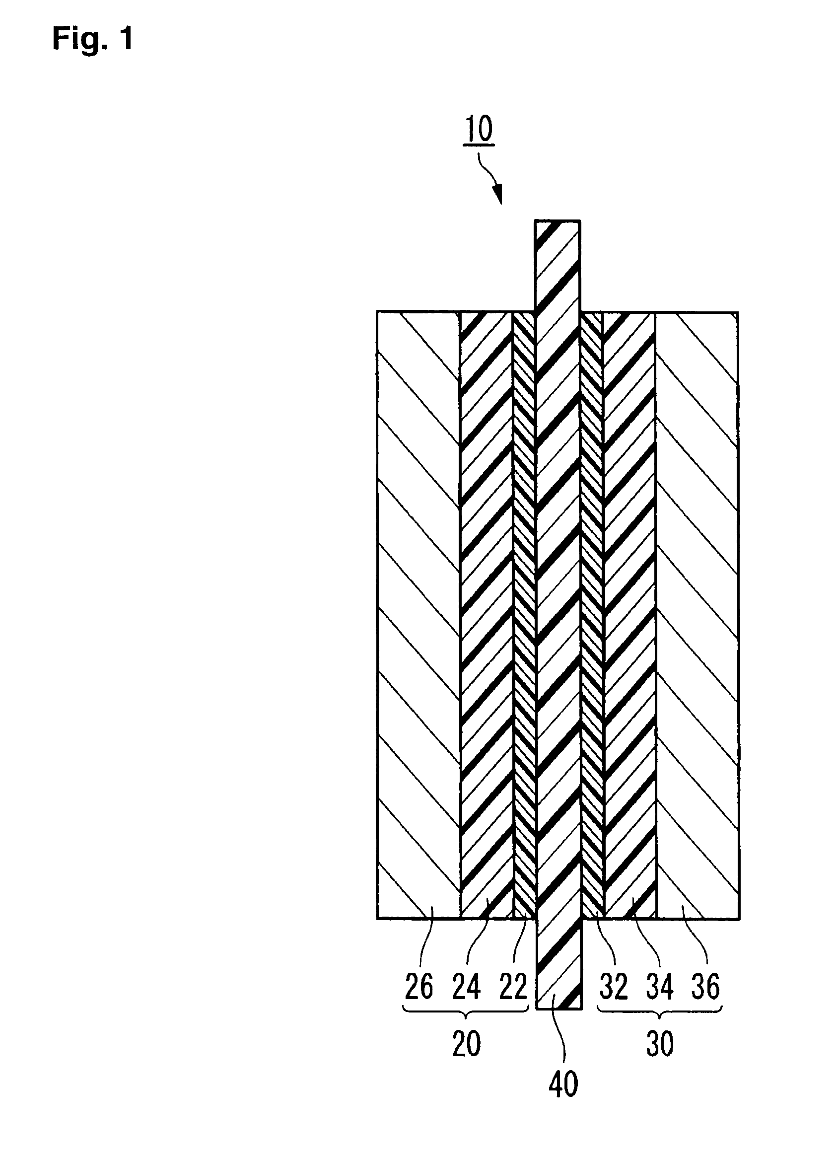
[0410]A polymer electrolyte membrane was formed as follows.
Preparation of Polymer (P1)
[0411]An autoclave (internal capacity: 2,575 cm3, made of stainless steel) was flushed with nitrogen to carry out deaeration sufficiently. Under reduced pressure, 950.3 g of compound (m12), 291.4 g of compound (m21), 490.1 g of compound (3-1) as a solvent, 173.7 mg of methanol and 873.1 mg of compound (4) (Peroyl IPP, manufactured by NOF Corporation) as a radical initiator, were introduced, and the interior of the autoclave was deaerated to the vapor pressure.
CClF2CF2CHClF (3-1),
(CH3)2CHOC(═O)OOC(═O)OCH(CH3)2 (4)
[0412]The internal temperature was raised to 40° C., and TFE was introduced into the autoclave and the pressure was adjusted to 0.44 MPaG (gauge pressure). While maintaining the temperature and the pressure to be constant, polymerization was carried out for 6.0 hours. Then, the interior of the autoclave was cooled to stop the polymerization, and the gas in the system was purged.
[0413]The ...
PUM
| Property | Measurement | Unit |
|---|---|---|
| Fraction | aaaaa | aaaaa |
| Fraction | aaaaa | aaaaa |
| Fraction | aaaaa | aaaaa |
Abstract
Description
Claims
Application Information